RC2HL tank Controller interface To interface low-cost Heng Long RC tank controller with Hobby Grade Radio system (specifications and design are subject to change without notice)
*Sound set code info is in "Sound Set Code" page
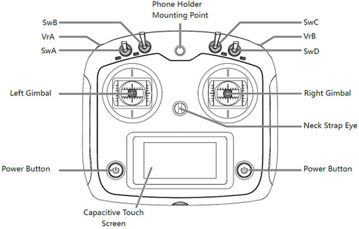
Transmitter: FS-i6S, self-centering VrA and VrB type Radio Assign SwB to CH7, SwC to CH8, VrA to CH9, VrB to CH10
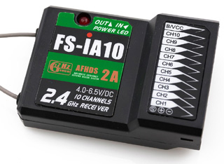
RX:FS-iA10
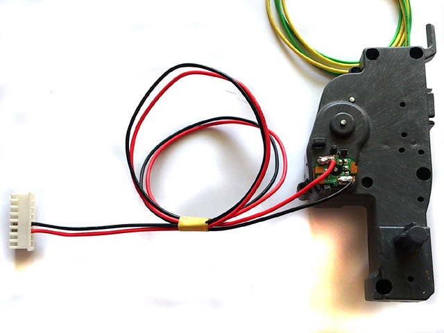
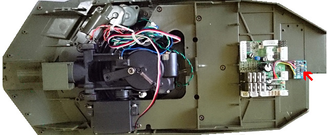
RC2HL series connector layout
RC2HL connector and pin assignments
Because HL tank already have power switch on battery cable path, so additional switch is not required, just to use a jumper to short pins in SW Cable port or connect a switch cable and keep it switched on.
When high current track motors are used, such as 400/480 motor, power switch on battery cable path will not be able to handle, connect a switch cable (for example, HL Smoke Unit Switch Cable) to this port as power switch.
When use F-4 Radio, connect receiver CH1~CH4 to TK20 CH1~CH4, Set transmitter control mode to mode 1, all reverser to REV position
TK20 board has BEC( Battery eliminate circuit), can power receiver through channel cables, no additional battery is needed for receiver
Installation Video Guide on Internet: https://www.youtube.com/watch?v=_eIRTIMyl2g
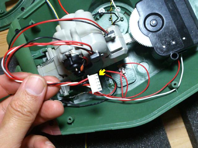
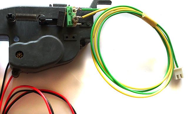
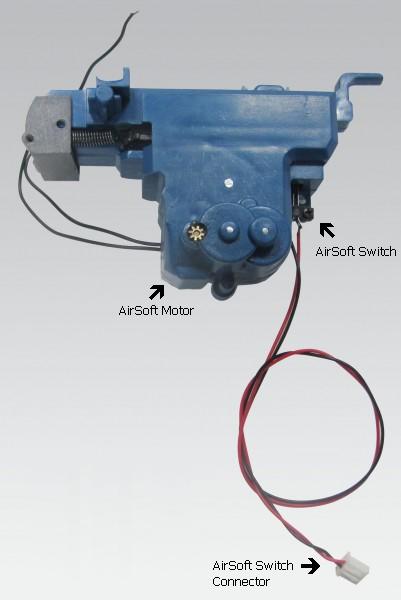
In HL original design, gun Elevation and AirSoft sharing same driving H/W, so the gun elevation can only be controlled in one direction, if you missed the angle you want, you will need to wait a full cycle of gun elevation, to correct this problem, we add dedicate AirSoft control h/w to TK20 board. the following shows you how to correct HL tank and get two direction elevation.
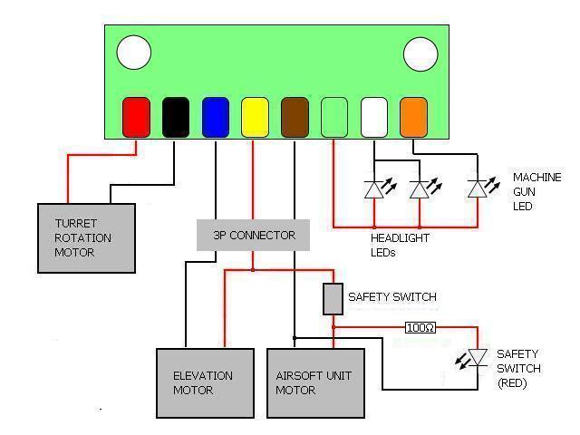
The picture below is original wiring in HL tank:
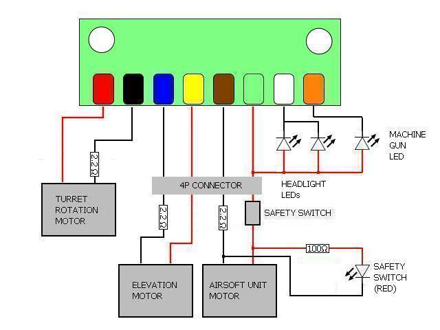
Modify it as the following:
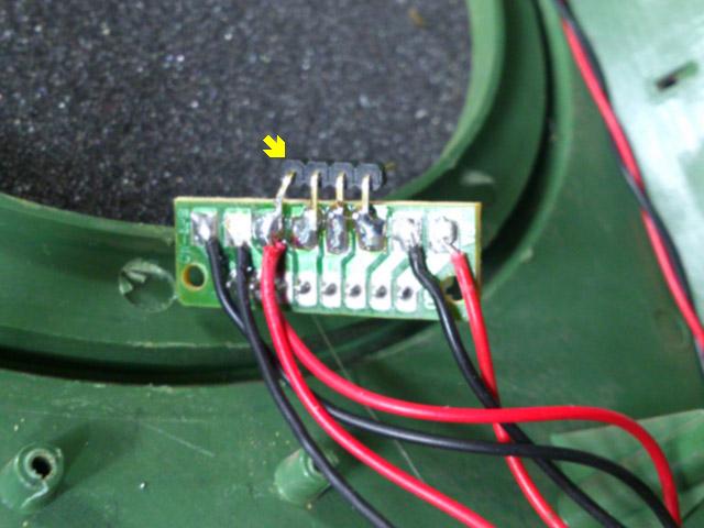
Green box in the diagram above represent the small PCB in tank, small red, black, blue ... orange in it represent the wire color.
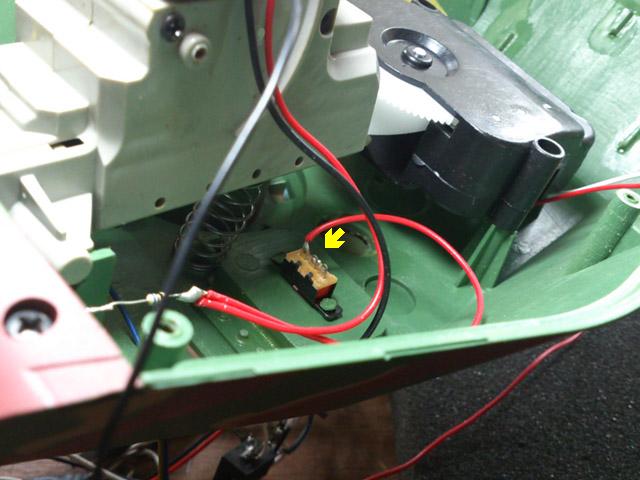
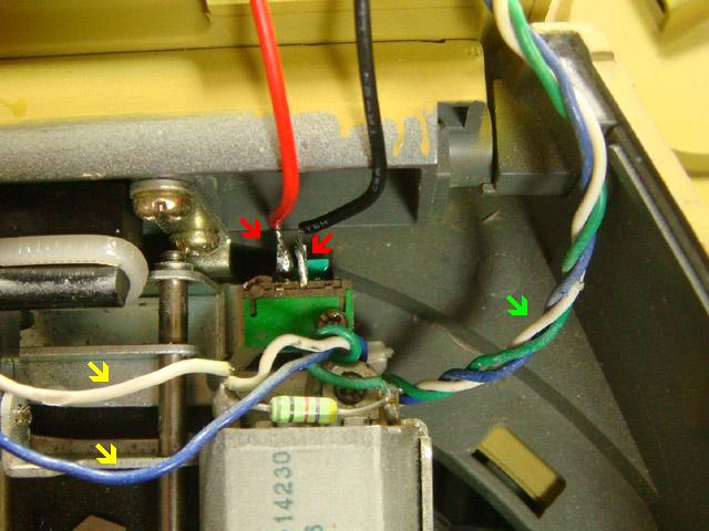
1. Disconnect red wire between safety switch and gun barrel elevation unit.
2. Change original 3P connector to 4P type, add additional wire from safety switch to 4P connector,
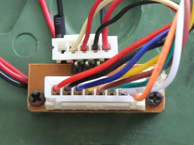
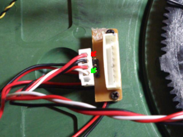
3. Add 4P connector HUL-8P PCB connector
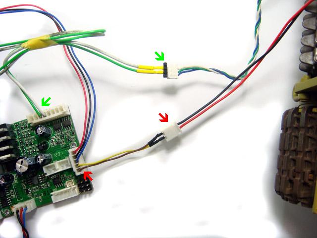
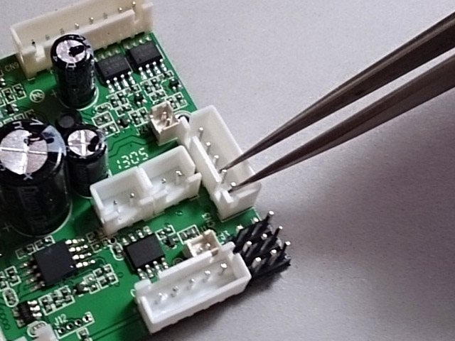
4. AirSoft unit is now controlled by red-black pair, gun barrel unit is controlled by red-white pair. and you can connect 8P connector to CN9 on TK-18/20 with original cable.
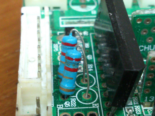
5(Optinal). refer to wiring diagram, wire a 2.2 ohm 1/2W (color code: red read gold gold) in-serial resistor to turret rotate, elevation and airsoft motor to limit the current to protect FETs on TK22 in case you stall motor.
2.2 ohm resistor can also be found on RX-18.
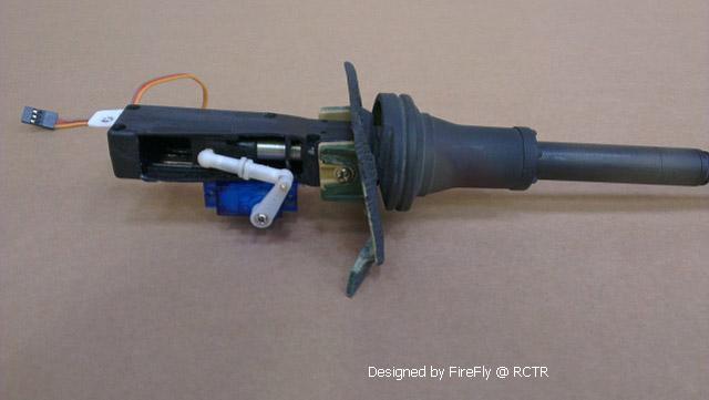
Here is a video of airsoft setup for Taigen Tank
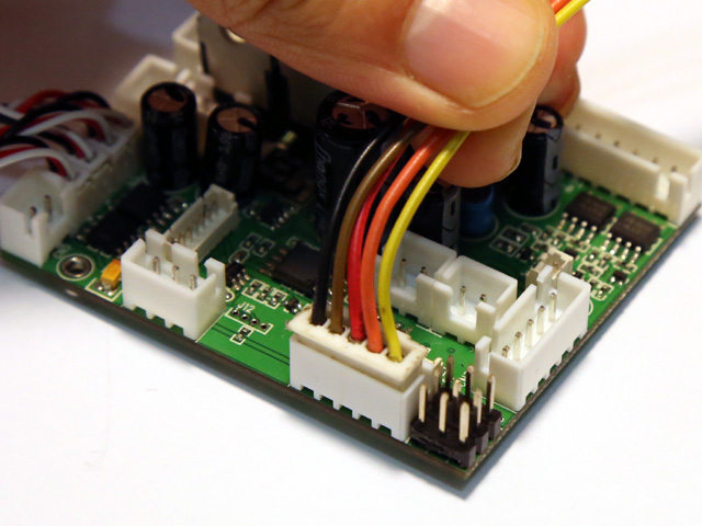
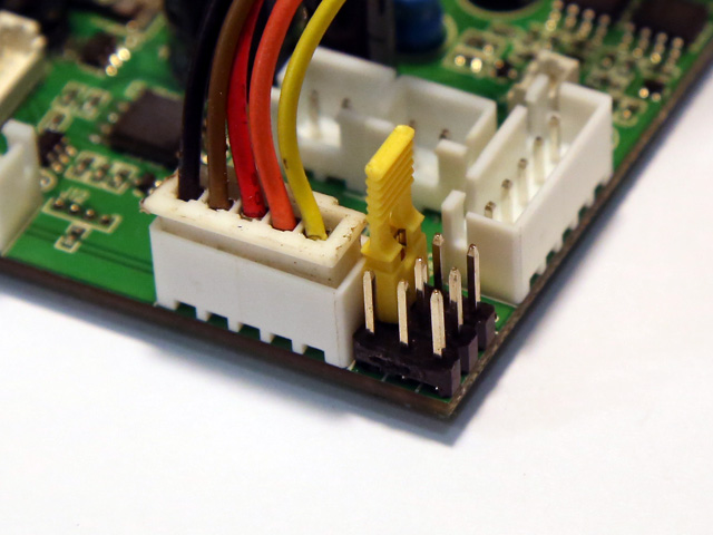
1. Remove 2 pin plug from PCB, twist angled pins to opposite side, 2. Connect Tail Light LED + pin( Red wire of Tail Light cable) to CN9.3 pin( Yellow wire ) 3. Connect a 200 Ohm resistor between 2-P connector pin and CN9.2 pin(Green), a SMD type resistor is used in this example to save space.
Original wiring diagram
Corrected wiring diagram
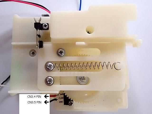
STEP1. disconnect white and blue wire from recoil unit switch( see arrow in yellow), add cable connector to recoil switch( see arrow in red ), left green-white-blue cable not touched ( see arrow in green)
STEP2. green wire and white wire in green-white-blue cable goes to 3rd pin on CN9 and 4th pin on CN9(see arrow in green), black and red wire in red-black cable goes to 4th and 5th pin on CN3(see arrow in red).
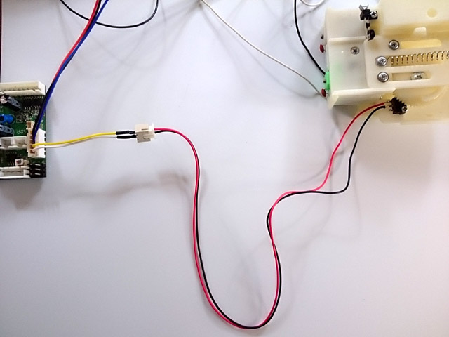
STEP1. Set Main Gun Function Mode to HL Recoil MODE, STEP2. Connect detection SW( Pressed-to-Short type ) to 4th and 5th pin on CN3 or via the plug (Yellow and brown wire) from HL HIGH-TENSION FLASHER. Latest released HL recoil unit already has detection switch on it.
STEP3. connect motor - to 4th pin on CN9.connect motor + to 3rd pin on CN9.
STEP1. Set Main Gun Function Mode to TAMIYA Recoil MODE, STEP2. Connect Recoil motor + to 3rd pin on CN9.connect motor - to 4th pin on CN9.
STEP2. Connect detection SW to 4th and 5th pin on CN3 or via the plug (Yellow and brown wire) from HL HIGH-TENSION FLASHER
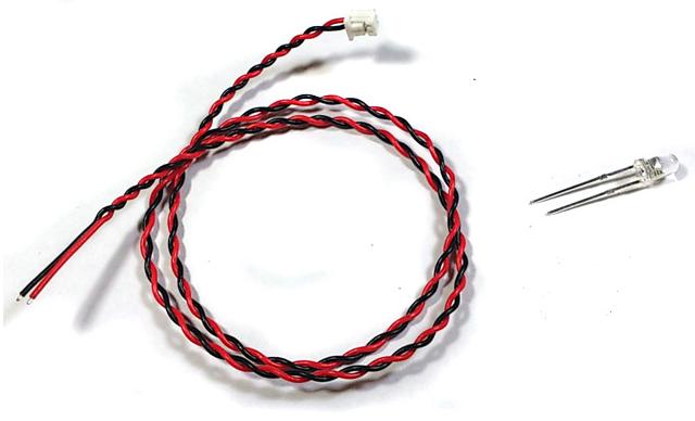
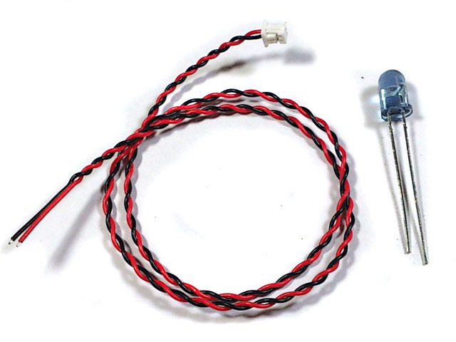
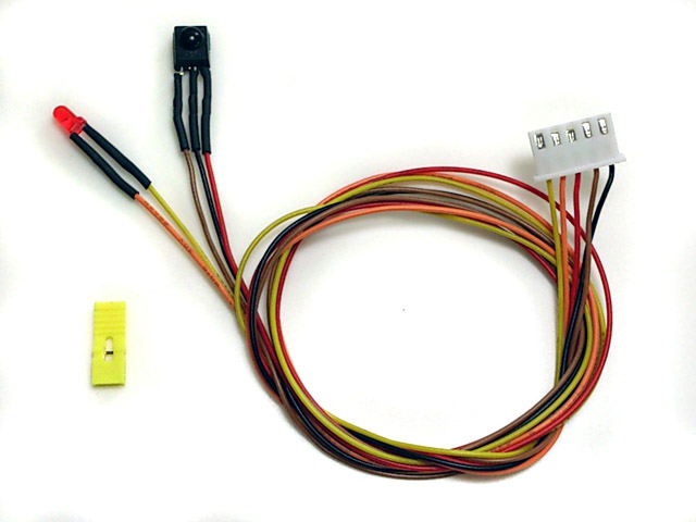
HL Hop-up options "HIGH-TENSION FLASHER" can be easily installed and works with TK20 to simulate gun nuzzle flash when firing.
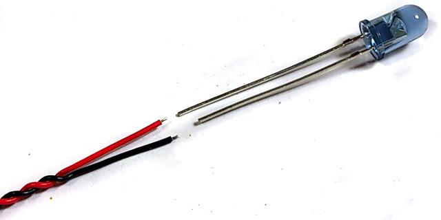
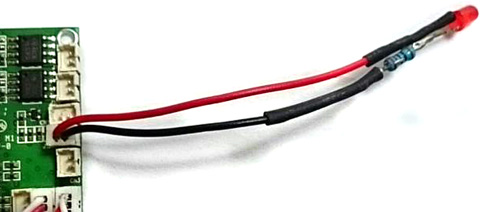
A white LED and cable connector are needed( Part Number is F003)
Solder color wire (red wire in this example) to long pin of white LED, black wire(-) to short pin,
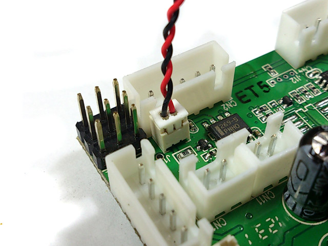
Plug cable into J3.
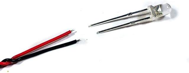
An IR LED and cable connector are needed( Part number is IR005/IR010 ).
Solder color wire (red wire in this example) to long pin of IR LED, black wire(-) to short pin,
Plug cable into J1.
GSU is an optional module of TK22. When GSU is turned on, it detects the tank movement and compensate gun rotation and elevation to stabilize the gun automatically. When GBS is turned on, operator can still change gun elevation and direction under GBS compensation, GSU have the following features:
- 2-axis gun stabilization in turret rotation and gun elevation.- Fully programmable gun elevation real angle calculator allows GBS to work with different elevation setup ,- Fully programmable turret motor controller allows GBS to work with different motor/gear box setup, - Engine deck detection, gun raise automatically when gun travels above engine deck,- Auto reload position, Gun barrel goes to to reload position after fire, and return to last position when reload when reload time expired, - Adjustable Engine deck level,- Adjustable auto reload position, - Gun barrel momentum effect, - GBS unit d imensions: 20 x 16 x 3mm.- Unified platform design, allows all existing TK20/TK22 can be shipped back to us to upgrade to TK22G2
Servo for GBS -
-Control System: +Pulse Width Control 1520usec
Neutral
-Operating Angle: 45 Deg. one side
Power on GBS
calibration - The GBS LED blinks during GBS calibration and you must not to move the tank during calibration. The GBS are very sensitive and you should not touch or vibrate the GSU during power on reset. The process will take a few seconds. The HEADLIGHT led will turn on when calibration completed. An in-series 200-ohm resistor is needed for GBS LED
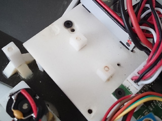
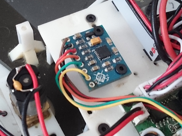
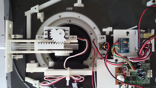
Mounting of GBS - The GBS unit must be mounted securely and horizontally on the turret, here is an example, first to use Tamiya 5mm square beam, cut into 5~6mm in length, make 1.6mm hole, then glue to turret floor by cement
Bolt GBS unit with the screws came with GBS unit, and plug connector to J6 port on TK22G2, Length of GBS cable can not exceed 80mm or TK22G2 may miss reading GBS.
For accurate motion detection, it must be kept within 5 degree with turret base plate. mounting directions is as shown in following picture. Servo for elevation is Futaba S3003 in this setup.
Recommended GBS mounting position for Leopard 2
Turning GBS on/off - GBS can be turned on/off by move right stick to top, move left stick to right, you can also hear click sound when turn it on and off
Adjusting gun elevation angle - The gun elevation V gain setting is used to adjust the amount of gun elevation servo angle to meet different mechanical setup. adjusting procedures are
-First to put TK22G board in IR programming mode. -Turn GBS on and moves the gun barrel to horizontal position. -Tilt the tank for 15-20 degree. -Use IR configure remote to adjust servo gain value until the gun is horizontal again. -Power off TK22G board, remove jumper and turn power again to leave IR programming mode.
Adjusting gun elevation angle calculator gains - The angle calculator's fast gain and slow gain settings are used to adjust the angle calculation, adjusting procedures are
-First to put TK60G2 board in IR programming mode. -Turn GBS on and moves the gun barrel to horizontal position. -Tilt the tank for 10-20 degree. -Rotate turret in various speed ( from low to full speed), if elevation speed is too slow, increase slow gain a bit, otherwise, reduce slow gain, -rotate turret to 12 o'clock position, tilt the tank hull about 15-20 degree in various speed, if elevation speed is too slow, can not keep up tank hull tilt speed, increase fast gain a bit, if elevation moves faster the hull tile speed and over the position it should be (overshoot), decrease fast gain a bit -Power off TK60G2 board, remove jumper and turn power again to leave IR programming mode.
Adjusting turret rotation motor control gains -Turret rotation motor P , I and D gain are used to meet the characteristic of turret rotate motor and design on your tank. adjusting procedures are as the following.
-First to put TK2xG2 board in IR programming mode. -Turn GSU on -Rotate tank hull from stationary to low speed, if turret motor does not start as quick as tank hull rotation, increase I gain a bit, if turret motor runs too fast (overshoot) , decrease I gain a bit. -Rotate tank hull in various speed( low, middle and full) , if turret rotation speed is too slow, can't keep up hull rotation, increase P gain, otherwise, reduce speed gain, -Stop tank hull rotation from various speed, if turret stops too early, decrease D gain, if turret stops too late increase D gain.
Settings of TK series board can be changed by Configuration IR REMOTE as IR command transmitter, and TAMIYA battle unit(TBU), Heng-Leog battle unit(HBU), or our programming line as IR command receiver.
STEP 1: Turn power off, Turn power off, Turn power off, STEP 2: Plug programming line/TBU/HBU through TBU/HBU base into CN2 Infrared Port ,
STEP 2: Install a jumper to J2 as shown below, Turn power on,
STEP 4:Refer to function table listed below, point Configuration IR REMOTE to TBU/HBU/Programming line receiver, and press the button of setting that you want to change, "*" sign in function table means the default setting that is programmed in factory
STEP 5: Indicator on TBU/HBU flashes according to new setting value. STEP 6: turn power off, remove jumper on J2, then turn power on and TK board runs with new settings.
Type of Tank determines Battle Date when doing IR battle( See Variants section )
Note: HENG-LONG TANK doesn't have Damaged State and Badly Damaged State. speed reduction can be turned off by Speed reduction in damage state and Speed reduction in badly damaged state function.
Note: Suggested Value, can be changed by Reload Time and Invulnerability time setting function
Save current setting to PRESET 1: Press number key "1" on IR Configuration Remote to save,
Save current setting to PRESET 2: Press number key "2" on IR Configuration Remote to save,
*Once you've adjusted everything, you can push "1" or "2" to save current setting to PRESET 1 or 2. If you don't do this saving the board remembers the last settings.
Use saved settings: Press "ENT" or "SOUND MODE" Key on IR Configuration Remote to select.
*To switch between the presets you press either "sound mode" or "enter" button, once the preset is selected, switch tank off and remove setup jumper. Switch back on and away you go.
Mixer Mode:
Press
*pivot turn is also named as super spin.
Main Gun Function Mode: Press "POWER" key on IR Configuration Remote to select
*Use this mode on Hooben Tank. ** TK24 default setting
Receive TAMIYA IR Code: press "TV/VIDEO" or "->[]" Key on IR Configuration Remote to select
Receive HL IR Code: press "VOL DOWN" Key on IR Configuration Remote to select
IR Battle Preset Data: press "MTS" or "A/B" Key on IR Configuration Remote to select
Note1: Reference setting for HL Tank
Momentum effect On/Off: Press "SLEEP(0x36)"
or "
*This function is only available on TK22
Reload Sound On/Off: Press "Timer
Off(0x3C)"
or "
*This function is only available on TK22
Taking a hit hull recoil On/Off: Press "JUMP(0x3B)" on IR Configuration Remote to select
*This function is only available on TK22
Strength of taking a hit hull recoil: Press "CH Up" or "PROGR +" key on IR Configuration Remote to select
Firing tank gun hull recoil On/Off: Press "SURROUND(0x29)" on IR Configuration Remote to select
*This function is only available on TK22
Strength of firing tank gun hull recoil: Press "VOL UP" key on IR Configuration Remote to select
RealRecoil servo direction: press "CH down" or "PROGR -" key on IR Configuration Remote to select
Gun elevation servo direction:
press " Teletext
ON(0x3F)" or "
*This function is only available on TK22
Speed reduction in damaged state: press "3" key on IR Configuration Remote to select.
Speed reduction in badly damaged state: press "DISPLAY" or "DRC-MF" key on IR Configuration Remote to select.
Armor type: press number key "9" on IR Configuration Remote to select
Sending IR code when firing machine gun: press number key "6" on IR Configuration Remote to select
Primary weapon reload time: press number key "4" on IR Configuration Remote to select
Rounds of Primary weapon: press number key "8" on IR Configuration Remote to select,
Primary weapon IR code: press number key "0" on IR Configuration Remote to select
Invulnerability time: Vehicle is Invulnerable during this period, press number key "7" on IR Configuration Remote to select
Max hit can take: Press number key "5" on IR Configuration Remote to select
*The following setting function is only available on TK22G2/TK24/TK24G2 Function Page Selection: Press "-/--" Key on IR Configuration Remote to select. for TK22G2 only
*Text in black means that setting function is on page1.
GBS LED enable: press "TV/VIDEO" or "->[]" Key on IR Configuration Remote to select
Elevation Sound Mode: press "SOUND Mode" Key on IR Configuration Remote to select
*Default setting for TK24 **Default setting for TK24G2
Horizontal GBS motor P gain increase: Select page 4 , press number key "1" on IR Configuration Remote to increase gain
Horizontal GBS motor P gain decrease: Select page 4 , press number key "4" on IR Configuration Remote to increase gain
Horizontal GBS motor I gain increase: Select page 4 , press number key "2" on IR Configuration Remote to increase gain
Horizontal GBS motor I gain decrease: Select page 4 , press number key "5" on IR Configuration Remote to increase gain
Horizontal GBS motor D gain increase: Select page 4 , press number key "3" on IR Configuration Remote to increase gain
Horizontal GBS motor D gain decrease: Select page 4 , press number key "6" on IR Configuration Remote to increase gain
Horizontal GBS sensitive increase: Select page 4 , press number key "8" on IR Configuration Remote to increase gain
Horizontal GBS sensitive decrease: Select page 4 , press number key "0" on IR Configuration Remote to increase gain
Vertical GBS slow response gain increase: Select page 3 , press number key "1" on IR Configuration Remote to increase gain
Vertical GBS slow response gain decrease: Select page 3 , press number key "4" on IR Configuration Remote to increase gain
Vertical GBS fast response gain increase: Select page 3 , press number key "2" on IR Configuration Remote to increase gain
Vertical GBS fast response gain decrease: Select page 3 , press number key "5" on IR Configuration Remote to increase gain
Vertical GBS servo angle gain increase: Select page 3 , press number key "8" on IR Configuration Remote to increase gain
Vertical GBS servo angle gain decrease: Select page 3 , press number key "0" on IR Configuration Remote to increase gain
Engine deck level increase: Select page 3 , press "VOL UP" on IR Configuration Remote to increase level Engine deck level decrease: Select page 3 , press "VOL Down" on IR Configuration Remote to decrease level Engine deck level Function Enable: Select page 3, press "MUTE" Key on IR Configuration Remote to select
Auto Load Position UP: Select page 3 , press "CH UP" on IR Configuration Remote to increase level Auto Load Position Down: Select page 3 , press "CH Down" on IR Configuration Remote to decrease level Auto Load Position Function Enable: Select page 3, press "POWER" Key on IR Configuration Remote to select
Point Configuration IR remote to TBU/HBU and press key listed below to show vehicle status or test IR battle function. No jumper should be installed on J1.
Q: Can I use GSU on TK22 or TK22. A: No, GSU can only work with TK22G1 or TK22G2. existing TK22 board can be returned to upgrade to TK22G1/G2 with upgrade fee.
Q: My Tk22 can not register a hit from Tamiya tank. A: To check "Receive Tamiya IR code" setting. TK22 won't response Tamiay IR code when this setting is disabled.
Q:
The airsoft motor does not run until after the gun fire sound has played and the
reload sound has happened. I want the airsoft motor to run while the gun sound
plays. I also planned to make recoil work with the airsoft
but when I fire the
gun, the recoil servo operates in time to the sound
but has returned to the
normal position when the airsoft motor operates.
Q: I already set Main Gun Function Mode to HL AirSoft MODE, but AirSoft motor does not run when I give fire cannon command. A:To correct airsoft unit wiring as HL Gun Elevation and AirSoft Correction section mentioned.
Q: Airsoft unit fires continuously and have no cannon sound. A: When main Main Gun Function Mode is configured to AirSoft Mode, TK22/20 start to drive AirSoft motor (thought CN9 3rd &4th pin) when fire cannon command is received. when Airsoft just fired, Airsoft switch is closed , Tk22 knows it thought CN3 Pin4 & Pin5. and then stop to drive Airsoft Motor and start to generate cannon. So in order to make it works properly, AirSoft motor need to be connected to CN9 pin3 and pin4. AirSoft switch connector to CN3 Pin4 & Pin5.
You can simply test it by a tweezers, to short and release it will stop AirSoft motor.
Q:
How to avoid damage that caused by short circuit to the board?
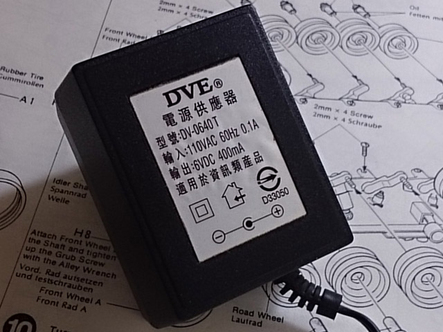
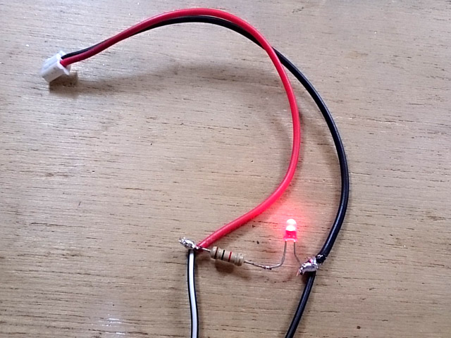
then connect + wire(with white strip) from adaptor to red wire of HL cable, - wire to black wire of HL cable, adn wire resistor and LED as the following to act as indicator.
Each time, when you did some modification on circuit or after installation, use this as power source fist. plug connect each by each, and LED will be dimmed immediately if any shortage in circuitry and not thing on TK board will be damaged because power can only supply low & limited current.
The board might be act very strange when it's power by this, such as motor can not moves will, cannon fired unexpectedly when turret rotation sound comes up, these are quite normal because current is not enough.
Q:
I accidentally shorted speaker wire and now had barely any sound, everything
still works but hardly any sound.
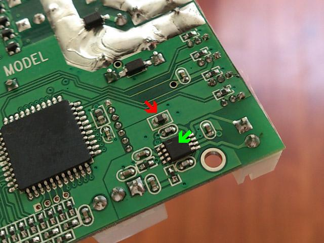
2nd, the audio amplifier ( pointed by green arrow) goes very hot when operating, do not apply glue or double faced adhesive tape on it and left some space for it for heat dissipation.
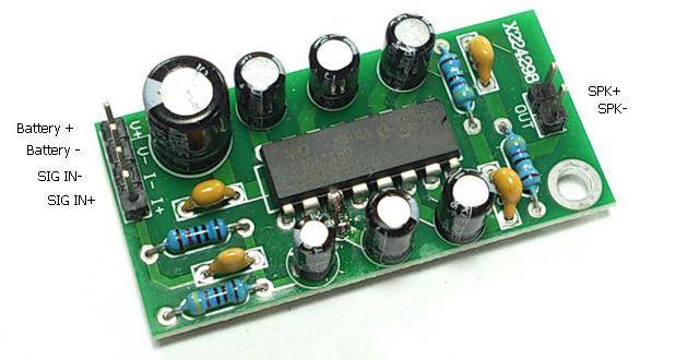
Q:
How to interface TK22 board to 6W external
sound booster(amplifier)
First
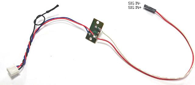
to disconnect black wire from HL Volume control board and isolate it with tape,
wire a 2-P, 2.54mm pitch connector wire to Volume control board as shown below Then to power amplifier by battery
Finally, connect power form TK22 to Battery+ & Battery - pin, connect 2-P, 2.54mm pitch connector wire SIG+ and SIG-,and then connect sparker to SPK+ and SPK- pin.
Here is pin assignment of another type 6W AMP, just refer to the above and wire pins with same pin assignment.
Generally, higher the input power, higher the sound output power on speaker, so we can also use a DC-to-DC voltage booster to convert battery voltage into higher voltage, then to drive external audio amplifier to have more solid and powerful sound,
Because output ripple is much lower after DC-to-DC conversion, so this can also reduce motor "humm" sound during motor start up and at low speed. another benefit of this configuration is that you can use 8-ohm speaker but still have good loudness. In the example below, we use an adjustable DC-to-DC voltage booster to convert battery voltage into 12V.
Step 1: first to connect AMP to TK board and battery as describe previous and make sure it sounds correctly,
Step 2: connect
DC-to-DC voltage booster to
battery only, measure the output voltage,
if voltage is higher or less than
12V, adjust VR on it till output voltage is around 12V,
HINT: use VR pointed by black arrow in this diagram to adjust voltage to 12V before powering amplifier
Wiring diagram for 15W amplifier: Use VR on DC/DC converter to set output voltage to 15V
Q:
When I move left stick backward, only the right track goes backward the left
track does not move, It is possible I crossed the +positive and --negative
terminals when connecting the new motors?
We recommend that to use power adapter(7.2V, 400mAh) as power source after rewiring. then switch to battery when everything are tested OK.
Q: Tank hull
recoil movement direction is not correct, moves forward and then backward while
firing main gun.
Q: All function runs but just no sound!! A: This can be the common issue on HL Volume Control board, just to short outer pins of CN4 with tweezers to verify it. if sound comes out when doing this, the HL volume control board is broken.
Q: Do I need noise filtering capacitor on motor A: Yes, it's needed to prevent back EMF to interference TK20 board. All HL stock tank already have it on motors
This type of capacitor is not good, DO NOT USE!
Q: What's the IR battle range of TK20 A: The table below shows the test result we've done here or from customer site,
Q:Tank moves backward faster than forwards and does not turn. It only turn if firstly turn steering stick and secondly throttle stick. A: To turn off mixer on transmitter and test again.
Q: Can get motor sounds, cannon sounds, turret sounds, but no motion on either drive motors or turret rotation gearbox A: Check if battery voltage is too low, auto cutoff function cuts motor off when battery voltage is too low.
Q: It is possible to change the sound? A: No, to change sound on TK board required some equipment and technique, so you can not do it by yourself, but we can if you send us processed sound file(22KHz, 8-Bit format) that you want to program into, average lead time is 2 weeks, This service is free of charge with MOQ( Minimum order quantity) of 3 units. The following are the sound effect section you can change.
- Cannon - Machine Gun - Gun elevation - Turret travels( 4 sections, start, loop1, loop2 & stop) - Engine Start, engine step 1~8, engine stop.
Q: What is Mixer
A: A piece of software
that converts
Rudder
Q: What is Safety shutoff: A: Controller cuts motor off and waits signal come back.
Q: What is Auto cutoff: A: The motor cutoff will occurred when battery input drops below minimum supply voltage of controller.
Q: Which RC system can works with RC2HL board: A: Basically, TK can work with all kind of aftermarket RC system as long as it's PWM system, here is a table list most popular one.
Q: Audio Amp thermal protection: A: that turns off device when junction temperature over 150 degree C to prevent damage
Q: Is it possible to make additional settings using existing IR signals for example to make HL IR signal and 9 hits can take, originally 5 hits? A: yes, IR code to receive, IR code to transmit, preset & battle data can be set independently.
Q: Is it possible to set setting with other device (not SONY IR code remote)? A: Only Sony IR code remote can be used, you can also have universal remote and configure it to SONY mode.
Q: Any Other
SONY remote, such as SONY Bravia unified IR
Configuration Remote, can config TK20?
Q: What's BEC A: BEC stands for battery elimination circuit. This circuit powers the receiver thought channel cable, no secondary battery source is required.
Q:
I would like to convert my VSTank PRO 2.4ghz
King Tiger AirSoft to full proportional control. A: You need followings
TK22: for main board,
MADE IN TAIWAN
|
|||||||||||||||||||||||||||||||||||||||||||||||||||||||||||||||||||||||||||||||||||||||||||||||||||||||||||||||||||||||||||||||||||||||||||||||||||||||||||||||||||||||||||||||||||||||||||||||||||||||||||||||||||||||||||||||||||||||||||||||||||||||||||||||||||||||||||||||||||||||||||||||||||||||||||||||||||||||||||||||||||||||||||||||||||||||||||||||||||||||||||||||||||||||||||||||||||||||||||||||||||||||||||||||||||||||||||||||||||||||||||||||||||||||||||||||||||||||||||||||||||||||||||||||||||||||||||||||||||||||||||||||||||||||||||||||||||||||||||||||||||||||||||||||||||||||||||||||||||||||||||||||||||||||||||||||||||||||||||||||||||||||||||||||||||||||||||||||||||||||||||||||||||||||||||||||||||||||||||||||||||||||||||||||||||||||||||||||||||||||||||||||||||||||||||||||||||||||||||||||||||||||||||||||||||||||||||||||||||||||||||||||||||||||||||||||||||||||||||||||||||||||||||||||||||||||||||||||||||||||||||||||||||||||||||||||||||||||||||||||||||||||||||||||||||||||||||||||||||||||
|
|
|||||||||||||||||||||||||||||||||||||||||||||||||||||||||||||||||||||||||||||||||||||||||||||||||||||||||||||||||||||||||||||||||||||||||||||||||||||||||||||||||||||||||||||||||||||||||||||||||||||||||||||||||||||||||||||||||||||||||||||||||||||||||||||||||||||||||||||||||||||||||||||||||||||||||||||||||||||||||||||||||||||||||||||||||||||||||||||||||||||||||||||||||||||||||||||||||||||||||||||||||||||||||||||||||||||||||||||||||||||||||||||||||||||||||||||||||||||||||||||||||||||||||||||||||||||||||||||||||||||||||||||||||||||||||||||||||||||||||||||||||||||||||||||||||||||||||||||||||||||||||||||||||||||||||||||||||||||||||||||||||||||||||||||||||||||||||||||||||||||||||||||||||||||||||||||||||||||||||||||||||||||||||||||||||||||||||||||||||||||||||||||||||||||||||||||||||||||||||||||||||||||||||||||||||||||||||||||||||||||||||||||||||||||||||||||||||||||||||||||||||||||||||||||||||||||||||||||||||||||||||||||||||||||||||||||||||||||||||||||||||||||||||||||||||||||||||||||||||||||||