|
MTK37/40 Series RC
Military Truck Controller

To
upgrading Heng Long 1/16 Military
Truck into
proportional radio control with IR battle, Light and realistic sound Effect
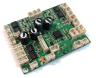
Overview
- MTK series controller
uses 4-CH PWM or 10-CH S.BUS RC system to control 1/16 R/C truck
forward/backward movement, turning and weapon,
- Miniature design
allowed your to
keep interior of
diver cabin,
-
Ultrasonic
ESC for propulsion motor and steering
-
Adjustable ESC start voltage allows you to adjust lowest speed for track
motor
- Carefree reversing
- Ultra Low turn-on resistance
FET for track motor ESC
-
Steering
Motor
ESC to drive
stock steering box,
- ESC/PWM module( EPM) can be
used as gun elevation/traverse control or other applications
-
Max.3W
sound output power,
-
V2 Smoker driver
- Safety shutoff prevents
unwanted movement while signal lost,
-
Maximum of 5 channel of
sound effect can be generated at the same
time, such as
Terminology
ESC/PWM
module( EPM) is
peripheral which allows the user to
drive
brushed motor or servo motor, In ESC mode, ESC port is enabled, can be
used to drive brushed motor, In PWM mode, PWM port is enabled to driver
servo motor, sound effect stopped when servo motor reach end point
Ultrasonic
ESC is the ESC block which switch FET at ultrasonic speed, make motor
rotation very smooth and quite..
Variants
|
|
MTK40/S/P |
MTK37/P/S |
|
Remote Control System
|
Traditional 4-CH AM, FM
or
2.4G RC system with S.BUS |
Traditional 4-CH AM, FM
or
2.4G RC system with S.BUS |
|
Engine Sound Simulation
|
Multi
Simple Set Fuzzy Logic
|
Multi
Simple Set Fuzzy Logic
|
|
Motor driver Current
|
20A ( 130~480 Motor) |
7A ( N20~280 Motor) |
|
Audio Amplifier |
3W |
3W |
Release Schedule
|
Software
Package
Name |
Description/Notice/Change/New
Features |
Release Schedule |
|
V1 |
Initial Release, MTK37SP
|
Released |
|
V2 |
SW for Ver.2 Hardware board
|
Released |
|
PMW_V1 |
4-CH PWM
version MTK37 and MTK40 |
Released |
|
|
|
|
|
|
|
|
Hardware Change Notice
|
Version |
Description/Notice/Change/New
Features |
Release Schedule |
|
MTK37 Ver.1
|
Initial Production:
- ESC1 and PWM1 of EPM1 are both enabled |
Released |
|
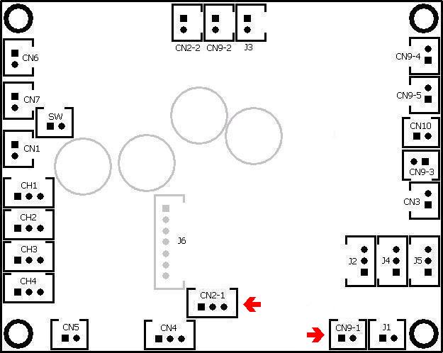
MTK37 Ver.2
|
2nd production:
- EPM1 can only works in ESC or PWM Mode
- CN2-1 and CN9-1 direction are changed |
2018. Feb |
Boot loader Release
Boot Loader is a application, executed in MTK
board, to handles software update, sound pack programming and setting data
update
|
Version |
Description/Notice/Change/New
Features |
Release Schedule |
|
Ver.2
|
-Auto Sound pack change detection
-Auto Clean at software update |
Released |
Product Identification System
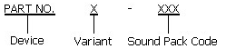
|
Device |
MTK40/37 |
MTK40/37 Military
Truck Controller |
| |
|
|
|
Variant |
Blank |
Standard 4-CH radio |
| |
S |
S.BUS interface |
| |
P |
Sound Programmable |
| |
|
|
|
Sound Pack |
M35A2 |
M35A2 Truck, multifuel, turbo |
| |
M35A1 |
M35A1 Truck, gas engine, turbo |
| |
M35 |
M35 Truck, gas engine |
| |
GAZ-66 |
GAZ-66 Truck |
|
..... |
Refer to TK Sound Pack webpage for more
information |
Ordering Information
|
Item No. |
Kit
Contained |
Price (USD) |
|
MTK40 |
MTK40
control board*1
Receiver cable *4
1.27mm 2P cable *10 |
110 |
|
MTK40P |
MTK40
control board*1
Receiver cable *4
1.27mm 2P cable *10 |
130 |
|
MTK40SP |
MTK40SP
control board*1
Receiver cable *4
1.27mm 2P cable *10 |
130 |
|
MTK37 |
MTK37
control board*1
Receiver cable *4
1.27mm 2P cable *15
1.27mm 3P cable *5 |
70 |
|
MTK37P |
MTK37
control board*1
Receiver cable *4
1.27mm 2P cable *15
1.27mm 3P cable *5 |
80 |
|
MTK37SP |
MTK37SP
control board*1
Receiver cable *4
1.27mm 2P cable *15
1.27mm 3P cable *8 |
90 |
Accessories
|
Part Number
|
Description
|
|
MTK-RECEIVER |
Micro 2.4G S.BUS
receiver for FlySky i6s |
|
MTK-SPK |
Speaker with
volume control |
|
MTK-CASE |
Casing
for MTK37 board and servo steering assembly |
|
CAB001 |
1.25mm pitch cable
connector for connecting IR LED or Gun Flash LED |
|
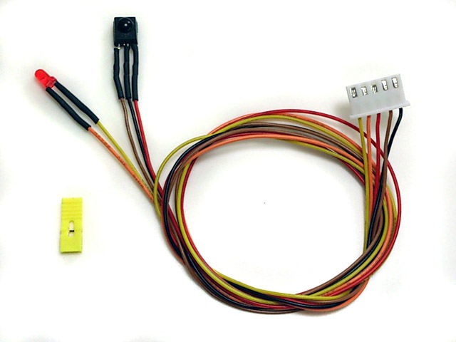
IR Programming Line |
5P connector with IR receiver
& Red LED indicator, and a 2.54mm-pitch Jumper
|
4-CH
Conventional PWM
mode
control
scheme
Receiver to MTK40/37 board connection
|
Receiver |
Connection |
|
CH1 |
MTK37/40 CH1 and Steering servo |
|
CH2 |
MTK37/40 CH2 |
|
CH3 |
MTK37/40 CH3 |
|
CH4 |
MTK37/40 CH4 |
|
i.Bus SERVO |
Not
connected |
|
i.Bus SENS |
Not
connected |
|
Layout |
Command |
Note |
|
  |
Repair Damaged Tank
修復坦克 |
修復坦克指示燈閃爍及音效 |
|
 |
Horn
喇叭 |
喇叭音效 |
|
  |
ESC2/PWM2
Forward/Backward
ESC2/PWM2
前進/後退
|
連接到ESC2的馬達正逆轉
或
連接到PWM2的伺服馬達左右擺動 |
|
 |
Left/Right Blinker
左/右方向燈
|
連接CN9-4左右方向燈閃爍 |
|
 |
Neutral Gear Shift In/Out
空檔(行走馬達解鎖) |
連接CN6的馬達正逆轉
連接CN7的馬達正逆轉 |
|
|
Engine sound on/off
引擎音效啟動 |
引擎音效啟動 |
|
 |
Fire MG
射擊機槍 |
產生機槍音效
連接CN9-1的LED閃爍 |
|
|
Head
light control on/off
頭燈開關 |
產生機槍音效
連接CN9-2的LED開或關
|
|
  |
Move forward
/ backward
行走馬達前進/後退
|
|
|
|
Right and
Left turn
左右轉
|
|
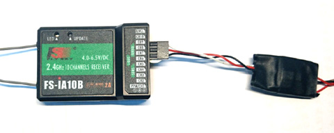
10-CH
S.BUS
mode
control
scheme
Transmitter: FS-i6S, self-centering VrA
and VrB type Radio
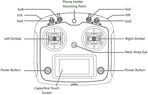
RX:FS-iA10B
Receiver to MTK24/37 board connection
|
Receiver |
MTK37/40 |
|
CH1 |
No connection |
|
CH2 |
No connection |
|
CH3 |
No connection |
|
CH4 |
No connection |
|
i.Bus SERVO |
Ver.1 Hardware: connect to CH1
on MTK37/40S/SP via a special S.BUS cable as the picture below
Ver.2 Hardware: connect to CH1
on MTK37/40S/SP via a receiver cable
|
|
i.Bus SENS |
No connection |
S.BUS cable for
Ver.1 Hardware
|
Layout |
Command |
S.BUS
Channel
assignment |
|
|
Right
and Left turn
|
CH1 (Stick) |
|
|
Move forward
and backward
|
CH2 (Stick) |
|
|
Ver.1
HW: ESC1 and PWM1 control
Ver.2 H/W: EPM1 control.
(
Ex. Elevation of weapon station) |
CH3
(Stick) |
|
|
ESC2
control(
Ex. rotation of weapon station) |
CH4
(Stick) |
|
SwB: Up
SwC: Center -> Up |
Natural Gear Shift In/Out
(test ok) |
Assign SwB to CH7
Assign SwC to CH8 |
|
SwB: UP
SwC: Center -> Down
|
Engine sound start/stop
(test
ok) |
Assign SwB to CH7
Assign SwC to CH8 |
|
SwB: Center
SwC: Center -> Up |
N/A |
Assign SwB to CH7
Assign SwC to CH8 |
|
SwB: Center
SwC: Center -> Down |
Hazard
flasher/Parking lamps On/Off
( test ok) |
Assign SwB to CH7
Assign SwC to CH8 |
|
SwB: Down
SwC: Center -> UP |
Smoke Unit
on/off (test ok)
|
Assign SwB to CH7
Assign
SwC to CH8 |
|
SwB: Down
SwC: Center -> Down |
Head
light On/Off ( test ok)
|
assign SwB to CH7
assign SwC to CH8 |
|
Key A |
Fire MG2 ( test ok) |
Assign KeyA to CH5 |
|
Key B |
Repair Damaged Tank (test ok) |
Assign KeyB to CH6 |
|
VrA |
Left:
Left Blinker: (test ok)
MID:
Right:
Right Blinker: (test ok)
|
assign VrA to CH9 |
|
VrB |
UP: MG (Ex. Hull mount MG )(test oK)
MID:
Down: Horn (test oK)
|
Assign VrB to CH10 |
Electrical
Specification
MTK37
|
Parameter
|
|
Unit
|
|
Maximum current of track ESC |
7 |
A |
|
Maximum current of turret and
cannon elevation ESC |
7 |
A |
|
Maximum current of Smoker Driver |
7 |
A |
|
Maximum supply
voltage |
11.4 |
V |
|
Minimum supply
voltage |
7.2 |
V |
|
On-board audio amplifier
Maximum power |
3 |
W |
MTK40
|
Parameter
|
|
Unit
|
|
Maximum current of track ESC |
20 |
A |
|
Maximum current of turret and
cannon elevation ESC |
7 |
A |
|
Maximum current of Smoker Driver |
7 |
A |
|
Maximum supply
voltage |
11.4 |
V |
|
Minimum supply
voltage |
7.2 |
V |
|
On-board audio amplifier
Maximum power |
3 |
W |
Connector and pin
assignments
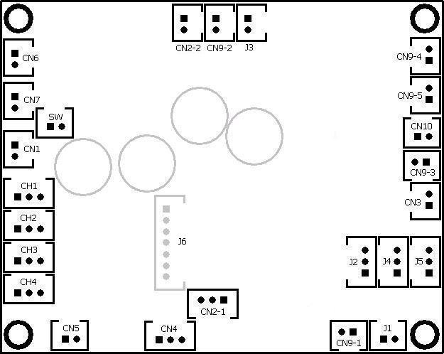
Ver.1 Hardware
Ver.2 Hardware
MTK37/MTK37P Connector
and pin assignments
|
Connector
|
Description
|
Pin assignments |
|
SW |
Switch Cable Port
開關 |
Connect to a switch |
|
CN1
|
Battery Power
電池
|
1. Battery +
2.
Battery -
|
|
CN2-1 |
Infrared RX Port
紅外對戰接收器 |
1.
HBU/TBU -
2.
HBU/TBU SIG
3.
HBU/TBU +
|
|
CN2-2 |
IR Battle indicator LED Port
紅外對戰指示燈 |
1. LED +
2. LED - |
|
CN3
(*1) |
N/A
無 |
1. Not Connected
2. Not Connected |
|
CN4 |
Sound
Volume
音量控制 |
1.
Volume Signal
Output (
Wiper pin of VR
)
2. Battery -( 1 outside pin of
VR )
3.
Volume
Signal
Input (
1 outside pin of VR ) |
|
CN5 |
Speaker
喇叭 |
1.
Speaker -
2.
Speaker +
|
|
CN6
(*x/1)
|
Propulsion/
Steering Motor
Motor
行走/轉向用馬達 |
1.
Motor+
2.
Motor- |
|
CN7
(*2/2)
|
Propulsion
Motor
行走用馬達 |
1.
Motor+
2.
Motor- |
|
CH1
|
Steering control
signal
轉向控制信號
|
Futaba: CH1
JR:AILE
*
Also connect CH1 signal to steering servo by Y cable
|
|
CH2
|
Throttle
control
signal
行走用馬達控制信號
|
Futaba:
CH2( Mode 2) or CH3 ( Mode 1 )
JR:ELEV
|
|
CH3 |
Multi function control
signal 1
多功能控制信號1 |
Futaba:
CH3( Mode 2) or CH2 (
Mode 1 )
JR:THRO
|
|
CH4
|
Multi function control
signal 2
多功能控制信號1
|
Futaba: CH4
JR:RUOD
|
|
CN9-1 |
MG LED
機槍燈 |
1.
MG
LED+
2.
MG
LED-
|
|
CN9-2 |
Head Light
頭燈 |
1.
Head Light LED+
2.
Head Light LED-
|
|
CN9-3 |
Reverse Light
倒車燈 |
1.--->200ohm in-serial resistor---->
LED
+
2.
LED
-
Maximum Current : 7A
*Need
200ohm in-serial resistor when connecting LED
|
|
CN9-4
(*0/4) |
Left and Right Blinker
左右方向燈
|
1.
--->200ohm
in-serial resistor---->
Right BlinkerLED
+,
--->Left
Blinker LED-
2.
--->200ohm in-serial resistor---->
Left BlinkerLED
+,
--->Right
Blinker LED-
|
|
CN9-5
(*1/3) |
ESC2
第二電子變速器 |
ESC port
for EPM2
1.
ESC2+
2.
ESC2-
|
|
CN10
(*3/0) |
Smoke unit
發煙器 |
1. Smoke
unit +
2. Smoke
unit - |
|
J1 |
IR Battle Emitter
Port
紅外對戰發射器 |
To work
with IR battle emitter(IR010)
1. IR LED +
2. IR LED - |
|
J2
(*5/5) |
N/A
無 |
1.
Not connected
2.
Not connected
3.
Not Connected |
|
J3 |
Repair tank indicator/Boot
loader Indicator
修復坦克指示燈 |
To
connect a
LED
1. LED +
2. LED - |
|
J4
(*1/4) |
N/A
無 |
1.
Not connected
2.
Not connected
3.
Not Connected |
|
J5
(*3/3) |
PWM2
第二PWM |
PWM
port for EPM2
1. Battery - (Black Wire)
2.
+5V ( Red Wire)
3. Signal( White Wire)
* Can
be used as Gun elevation control |
|
J6 |
Sound Programming
Port
音效燒錄插座 |
Connect
to TK Programmer
*For
sound programmable version
|
MTK37S/MTK37SP Connector and pin
assignments
|
Connector
|
Description
|
Pin assignments |
|
SW |
Switch Cable Port
開關 |
Connect to a switch |
|
CN1
|
Battery Power
電池
|
1. Battery +
2.
Battery -
|
|
CN2-1 |
Infrared RX Port
紅外對戰接收器 |
1.
HBU/TBU -
2.
HBU/TBU SIG
3.
HBU/TBU +
*Direction of connector is changed
|
|
CN2-2 |
IR Battle indicator LED Port
紅外對戰指示燈 |
1. LED +
2. LED - |
|
CN3
(*1/x) |
N/A
無 |
1. Not Connected
2. Not Connected |
|
CN4 |
Sound
Volume
音量控制 |
1.
Volume Signal
Output (
Wiper pin of VR
)
2. Battery -( 1 outside pin of
VR )
3.
Volume
Signal
Input (
1 outside pin of VR ) |
|
CN5 |
Speaker
喇叭 |
1.
Speaker -
2.
Speaker +
|
|
CN6
(*x/1)
|
Propulsion/
Steering Motor
Motor
行走/轉向用馬達 |
1.
Motor+
2.
Motor- |
|
CN7
(*2/2)
|
Propulsion
Motor port
行走用馬達 |
1.
Motor+
2.
Motor- |
|
CH1 |
S.BUS
S.BUS插座 |
1. Battery -
2.
+5V
3. Signal |
|
CH2 |
MG2 LED
第二機槍燈光 |
Connect to a GBS/MG2
LED:
Ver.1 Hardware:
1. Not Connected
2. --->200ohm in-serial resistor --> LED +
3.
LED -
Ver.2 Hardware:
1. Not Connected
2. LED +
3.
LED -
|
|
CH3 |
Right Blinker
右方向燈 |
Connect to a
LED:
Ver.1 Hardware:
1. Not Connected
2. --->200ohm in-serial resistor --> LED +
3.
LED -
Ver.2 Hardware:
1. Not Connected
2. LED +
3.
LED -
|
|
CH4 |
Left Blinker
左方向燈
|
Connect to a
LED:
Ver.1 Hardware:
1. Not Connected
2. --->200ohm in-serial resistor --> LED +
3.
LED -
Ver.2 Hardware:
1. Not Connected
2. LED +
3.
LED -
|
|
CN9-1 |
MG LED
機槍燈光 |
1.
MG
LED+
2.
MG LED-
*Direction of connector is changed
|
|
CN9-2 |
Head Light
頭燈 |
1.
Head Light LED+
2. Head
Light LED-
|
|
CN9-3 |
Reverse Light
後退燈 |
1.--->200ohm in-serial resistor---->
LED
+
2.
LED
-
Maximum Current : 7A
*Need
200ohm in-serial resistor when connecting LED
|
|
CN9-4
(*0/4) |
ESC1
第一電子變速器 |
ESC port
for EPM1
1.
ESC1+
2.
ESC1-
|
|
CN9-5
(*1/3) |
ESC2
第二電子變速器 |
ESC port
for EPM2
1.
ESC2+
2.
ESC2-
|
|
CN10
(*3/x) |
Smoke unit
發煙器 |
1. Smoke
unit +
2. Smoke
unit - |
|
J1 |
IR Battle Emitter
Port
紅外對戰發射器 |
To work
with IR battle emitter(IR010)
1. IR LED +
2. IR LED - |
|
J2
(*5/5) |
Steering Servo
Port
轉向伺服機
|
1. Battery -, connect to servo black/brown Wire
2.
+5V,
connect to servo red wire
3.
Not Connected |
|
J3 |
Repair tank indicator/Boot
loader Indicator
修復坦克指示燈 |
To
connect a
LED
1. LED +
2. LED - |
|
J4
(*1/4) |
PWM1
第一伺服機 |
PWM
port for EPM1
1. Battery - (Black Wire)
2.
+5V ( Red Wire)
3. Signal( White Wire)
* Can
be used as Gun elevation control |
|
J5
(*3/3) |
PWM2
第二伺服機 |
PWM
port for EPM2
1. Battery - (Black Wire)
2.
+5V ( Red Wire)
3. Signal( White Wire)
* Can
be used as Gun elevation control |
|
J6 |
Sound Programming
Port
音效燒錄插座 |
Connect
to TK Programmer
*For
sound programmable version
|
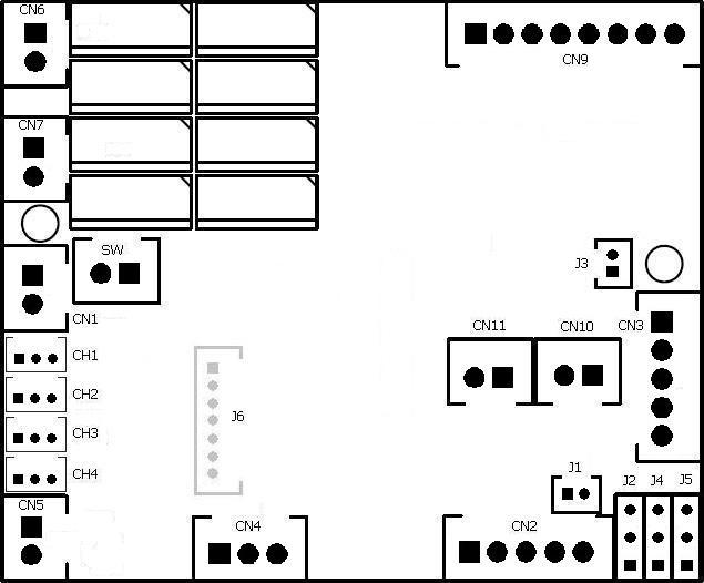
MTK40/MTK40P connector and pin
assignments
|
Connector
|
Description |
Pin assignments |
|
SW |
Switch Cable
Port |
Connect to a switch |
|
CN1 |
Battery
Power |
1. Battery +
2.
Battery - |
|
CN2 |
Infrared Port |
1.
HBU/TBU +
2.
HBU/TBU SIG
3.
HBU/TBU -
4. TBU FLASH LED -
5. TBU FLASH LED + |
|
CN3 |
Gun Flash
Port |
1.
Not Connected
2.
Not Connected
3.
Not Connected
4. Not Connected(*1)
5. Not Connected(*1) |
|
CN4 |
Sound Volume |
1.
Volume Signal
Output (
Wiper pin of VR
)
2. Battery -( 1 outside
pin of VR )
3.
Volume
Signal
Input (
1 outside pin of VR )
|
|
CN5 |
Speaker |
1.
Speaker -
2.
Speaker + |
|
CN6 |
Steering Motor
Motor |
1. Motor+
2. Motor-
|
|
CN7
(*2) |
Propulsion
Motor |
1. Motor+
2. Motor-
|
|
CH1
|
Steering control
signal
|
Futaba: CH1
JR:AILE
*
Also connect CH1 signal to steering servo by Y cable
|
|
CH2
|
Throttle
control
signal
|
Futaba:
CH2( Mode 2) or CH3 ( Mode 1 )
JR:ELEV
|
|
CH3 |
Multi function control
signal 1 |
Futaba:
CH3( Mode 2) or CH2 (
Mode 1 )
JR:THRO
|
|
CH4
|
Multi function control
signal 2
|
Futaba: CH4
JR:RUOD
|
|
CN9 |
Multi-Functions
|
1. MG LED-
2. Head Light LED-
3.
-
MG LED+,
-
Head Light LED+
-
Reverse Light
LED
+
4.
--->200ohm in-serial resistor---->
Reverse Light LED
-
5.
Connect to
6.
7.
ESC2
8.
ESC2
|
|
CN10
(*3) |
Smoke Unit |
Connect to smoke unit |
|
CN11 |
Smoke Unit Switch |
Connect to smoke unit switch
Switch on (Short circuit): smoke unit is
on
Switch off (Open circuit): smoke unit is
off |
|
J1 |
IR Battle Emitter
Port |
To work with IR battle
emitter(IR010)
1. IR LED +
2. IR LED - |
|
J2
(*5) |
N/A |
1.
Not connected
2.
Not connected
3.
Not Connected |
|
J3 |
Repair tank indicator/Boot
loader Indicator |
To
connect a
LED
1. LED +
2. LED - |
|
J4
(*4) |
N/A |
1.
Not connected
2.
Not connected
3.
Not Connected |
|
J5
(*3) |
PWM2 |
PWM port
for EPM2
1. Signal( White Wire)
2.
+5V ( Red Wire)
3. Battery - (Black Wire) |
|
J6 |
Sound Programming
Port |
Connect
to TK Programmer
|
MTK40S/MTK40SP connector and
pin assignments
|
Connector
|
Description |
Pin assignments |
|
SW |
Switch Cable
Port |
Connect to a switch |
|
CN1 |
Battery
Power |
1. Battery +
2.
Battery - |
|
CN2 |
Infrared Port |
1.
HBU/TBU +
2.
HBU/TBU SIG
3.
HBU/TBU -
4. TBU FLASH LED -
5. TBU FLASH LED + |
|
CN3 |
Gun Flash
Port |
1.
Not Connected
2.
Not Connected
3.
Not Connected
4. Not Connected(*1)
5. Not Connected(*1) |
|
CN4 |
Sound Volume |
1.
Volume Signal
Output (
Wiper pin of VR
)
2. Battery -( 1 outside
pin of VR )
3.
Volume
Signal
Input (
1 outside pin of VR )
|
|
CN5 |
Speaker |
1.
Speaker -
2.
Speaker + |
|
CN6 |
Steering Motor
Motor |
1. Motor+
2. Motor-
|
|
CN7
(*2) |
Propulsion
Motor |
1. Motor+
2. Motor-
|
|
CH1 |
S.BUS |
1. Signal
2.
+5V
3. Battery - |
|
CH2 |
MG2 LED |
Connect to a GBS/MG2
LED:
1. Not Connected
2. --->200ohm in-serial resistor --> LED +
3.
LED - |
|
CH3
(*2) |
Right Blinker |
Connect to a
LED:
1. Not Connected
2. --->200ohm in-serial resistor --> LED +
3.
LED - |
|
CH4 |
Left Blinker
|
Connect to a
LED:
1. Not Connected
2. --->200ohm in-serial resistor --> LED +
3.
LED - |
|
CN9 |
Multi-Functions
|
1. MG LED-
2. Head Light LED-
3.
-
MG LED+,
-
Head Light LED+
-
Reverse Light
LED
+
4.
--->200ohm in-serial resistor---->
Reverse Light LED
-
5.
ESC1
6.
ESC1
7.
ESC2
8.
ESC2 |
|
CN10
(*3) |
Smoke Unit |
Connect to smoke unit |
|
CN11 |
Smoke Unit Switch |
Connect to smoke unit switch
Switch on (Short circuit): smoke unit is
on
Switch off (Open circuit): smoke unit is
off |
|
J1 |
IR Battle Emitter
Port |
To work with IR battle
emitter(IR010)
1. IR LED +
2. IR LED - |
|
J2
(*5) |
Steering
Servo
Port
|
1. Battery -, connect to servo black/brown Wire
2.
+5V,
connect to servo red wire
3.
Not Connected
*Only available on TK24S/SP |
|
J3 |
Repair tank indicator/Boot
loader Indicator |
1. LED +
2. LED - |
|
J4
(*4) |
PWM1 |
PWM port
for EPM1
1. Signal( White Wire)
2.
+5V ( Red Wire)
3. Battery - (Black Wire) |
|
J5
(*3) |
PWM2 |
PWM port
for EPM2
1. Signal( White Wire)
2.
+5V ( Red Wire)
3. Battery - (Black Wire) |
|
J6 |
Sound Programming
Port |
Connect
to TK Programmer
|
Under construction!
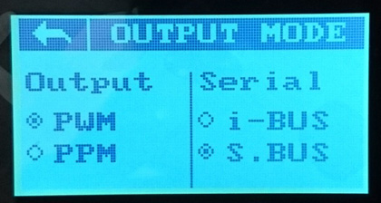
S.BUS setup
Transmitter:
1.Turn on Transmitter i6s and enter setting
function, go to system->output mode, than set Serial to S.BUS
2. Enter aux channel setup, set
channel 5 to SwA, channel 6 to SwD, channel 7 to SwB, channel 8 to SwC, channel
9 to VrA and channel 10 to VrB
Receiver and control board:
1. Plug connector with S.BUS
label on it into S.BUS port on receiver.
|
Personalization( Patent Pending) |
Settings
of MTK series board can be set by
IR
cconfiguration remote and programming line(
as follow)
 Steps
to set parameters:
Steps
to set parameters:
STEP 1: Turn power off,
plug programming line
to CN2,
STEP 2: Install a jumper to J2
as shown below, turn power on,
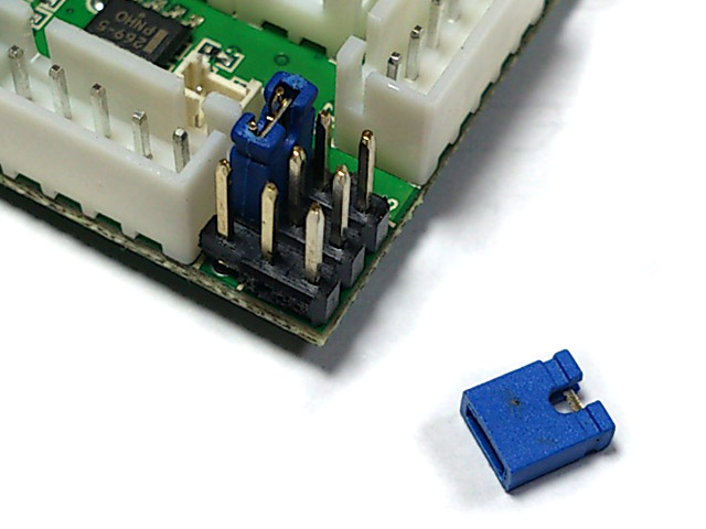
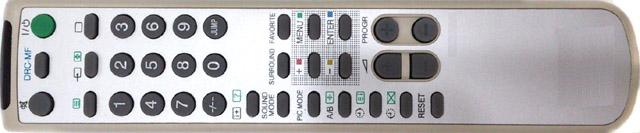
STEP 3: Point
IR Configuration remote to
programming line
receiver,
refer to function table listed below and press the button
of function that you want to set,
STEP 4: Indicator
of programming line flashes according to
the setting value.
STEP 5: turn power off, remove
jumper on J2, then power on and you are set.
Function tables:
Function Page Selection:
Press "-/--" Key on IR Configuration Remote to
select.
|
Available Settings |
Indicator
flashes times |
Description |
|
Select
settings on Page 1 |
1* |
TK board
goes back to this page after power on |
|
Select settings on Page 2
|
2 |
|
|
Select settings on Page 3
|
3 |
|
|
Select settings on Page 4 |
4 |
|
*Text in black means that
setting function is on page1.
Function Page 1
Save
current setting to
PRESET 1: Press number
key "1" on
IR configuration remote to save,
|
Available Settings |
Indicator
flashes times |
Description |
|
Save to
PRESET 1 |
1 |
Indicator flashes when setting
is saved
|
Save
current setting to PRESET 2: Press number
key "2" on
IR configuration remote to save,
|
Available Settings |
Indicator
flashes times |
Description |
|
Save to
PRESET
2 |
2 |
Indicator flashes when setting
is saved
|
*Once
you've adjusted everything, you can
push "1" or
"2" to save
current setting to PRESET 1
or 2. If you don't do this saving the board remembers
the last settings.
Use saved settings:
Press "ENT" or "SOUND MODE" Key on
IR configuration remote to select.
|
Available Settings |
Indicator
flashes times |
Description |
|
Use
PRESET 1
setting |
1 |
|
|
Use
PRESET 2 setting |
2 |
|
|
Use Factory Default Setting
( Read-Only ) |
3 |
To
restore factory
default value in case of setting data is messed up. |
*To
switch between the presets you press either "sound
mode" or "enter" button, once the preset is selected,
switch tank off and remove setup jumper. Switch back on and away you
go.
IR
Battle Preset Data: press "MTS" or "A/B" Key on
IR configuration remote to select
|
Available Settings |
Indicator
flashes times |
Description |
|
Reserved |
1 |
|
|
Reserved |
2 |
|
|
Reserved |
3 |
|
|
Heavy Armored vehicle |
4 |
Invulnerability time = 15 seconds,
Max. cannon hit cam take = 3 hit
Max. MG hit can take = 24 hit. |
|
Medium
Armored vehicle |
5 |
Invulnerability time = 15 seconds,
Max. cannon hit can take = 3 hit
Max. MG hit can take = 16 hit. |
|
Light
Armored vehicle |
6* |
Invulnerability time = 15 seconds,
Max. cannon hit can take = 1 hit
Max. MG hit can take = 8 hit. |
|
Reserved |
7 |
|
|
Reserved |
8 |
|
Note1: Reference setting for HL
Tank
Momentum effect On/Off: Press "SLEEP(0x36)"
or " "
on IR configuration remote to select "
on IR configuration remote to select
|
Available Settings |
Indicator
flashes times |
Description |
|
Off |
1* |
|
|
ON |
2 |
|
Taking
a hit hull recoil On/Off: Press "JUMP(0x3B)"
on IR configuration remote to select
|
Available Settings |
Indicator
flashes times |
Description |
|
On |
1* |
|
|
Off |
2 |
|
Strength of
taking a hit hull recoil:
Press "CH Up" or
"PROGR +" key
on IR configuration remote to select
|
Available Settings |
Indicator
flashes times |
Description |
|
1 |
1 |
Small( 1 ) to Large( 16
)movement |
|
: |
: |
|
6 |
6* |
|
: |
: |
|
16 |
16 |
Speed
reduction
in damaged state:
press "3"
key on IR
Configuration Remote
to select.
|
Available Settings |
Indicator
flashes times |
Description |
|
-6.25% |
1 |
|
|
-12.5% |
2* |
|
|
-18.75% |
3 |
|
|
-25% |
4 |
|
|
-31.25% |
5 |
|
|
-37.5% |
6 |
|
|
-43.75% |
7 |
|
|
-50% |
8 |
|
Speed
reduction
in
badly damaged
state:
press "(?)","DISPLAY"
or "DRC-MF" key on
IR Configuration Remote to
select.
|
Available Settings |
Indicator
flashes times |
Description |
|
-6.25% |
1 |
|
|
-12.5% |
2 |
|
|
-18.75% |
3 |
|
|
-25% |
4* |
|
|
-31.25% |
5 |
|
|
-37.5% |
6 |
|
|
-43.75% |
7 |
|
|
-50% |
8 |
|
Armor type:
press number
key "9" on IR
configuration remote to select
|
Available Settings |
Indicator
flashes times |
Description |
|
Heavy Armor |
1 |
Resistance to machine gun
|
|
Soft
skin, like Trucks |
2* |
No resistance to machine gun
|
Sending IR code when firing
machine gun:
press number
key "6" on IR
configuration remote to select
|
Available Settings |
Indicator
flashes times |
Description |
|
Not
to send
MG
IR code
|
1 |
|
|
To send MG IR code |
2* |
|
Repair
time:
press number
key "4" on IR
Configuration Remote to select
|
Available Settings |
Indicator
flashes times |
Description |
|
3 seconds |
3 |
|
|
4 seconds |
4 |
|
|
5 seconds |
5 |
|
|
6 seconds |
6 |
|
|
7 seconds |
7 |
|
|
8 seconds |
8 |
|
|
9 seconds |
9* |
|
|
10
seconds |
10 |
|
|
11 seconds
|
11 |
|
|
12
seconds |
12 |
|
|
13
seconds |
13 |
|
|
14
seconds |
14 |
|
|
15
seconds |
15 |
|
Number
of repair that truck can do:
press number
key "8" on IR
Configuration Remote to select,
|
Available Settings |
Indicator
flashes times |
Description |
|
Not
limited |
1* |
|
|
8 times |
2 |
|
|
16 times |
3 |
|
|
24 times |
4 |
|
|
32 times |
5 |
|
|
40
times |
6 |
|
|
48 times |
7 |
|
|
56 times |
8 |
|
|
64 times |
9 |
|
|
72 times |
10 |
|
|
80 times |
11 |
|
|
88 times |
12 |
|
|
96
times |
13 |
|
|
104
times |
14 |
|
|
112
times |
15 |
|
|
120
times |
16 |
|
Invulnerability time:
Vehicle is Invulnerable during
this period,
press number
key "7" on IR
configuration remote to select
|
Available Settings |
Indicator
flashes times |
Description |
|
Infinite |
1 |
can not be recovered from destroyed mode, power on and off
to restart |
|
1 second |
2 |
|
|
2 seconds |
3 |
|
|
3 seconds |
4 |
|
|
4 seconds |
5 |
|
|
5 seconds |
6 |
|
|
6 seconds |
7 |
|
|
7 seconds |
8 |
|
|
8 seconds |
9 |
|
|
9 seconds |
10 |
|
|
10
seconds |
11 |
|
|
11
seconds
|
12 |
|
|
12
seconds |
13 |
|
|
13
seconds |
14 |
|
|
14
seconds |
15 |
|
|
15
seconds |
16* |
|
Max cannon hit can take:
Press number key "5"
on IR configuration remote to select
|
Available Settings |
Indicator
flashes times |
Description |
|
1 round |
1* |
|
|
2 rounds |
2 |
|
|
3 rounds |
3 |
|
|
4 rounds |
4 |
|
|
5 rounds |
5 |
|
|
6 rounds |
6 |
|
|
7 rounds |
7 |
|
|
8 rounds |
8 |
|
|
9 rounds |
9 |
|
|
10
rounds |
10 |
|
|
11
rounds |
11 |
|
|
12
rounds |
12 |
|
|
13
rounds |
13 |
|
|
14
rounds |
14 |
|
|
15
rounds |
15 |
|
Function Page 2
Dual
Propulsion
Motor
function:
press "
CH UP" key
on IR configuration remote to select
|
Available Settings |
Indicator
flashes times |
Description |
|
Off |
1 |
Steering Motor
Port is controlled by
Steering control
signal(
CH1) |
|
On |
2* |
Steering Motor
Port is controlled by
Throttle
control
signal (CH2) |
EPM1 Mode:
press "
1" key
on IR configuration remote to select
|
Available Settings |
Indicator
flashes times |
Description |
|
ESC Mode |
1* |
ESC1 enabled, PWM1
disabled |
|
PWM Mode |
2 |
ESC1 disabled, PWM1
enabled |
PWM1 Direction:
press "
CH Down" key
on IR configuration remote to select
|
Available Settings |
Indicator
flashes times |
Description |
|
Normal |
1* |
|
|
Reversed |
2 |
|
EPM2 Mode:
press "
3" key
on IR configuration remote to select
|
Available Settings |
Indicator
flashes times |
Description |
|
ESC Mode |
1* |
ESC2 enabled, PWM2
disabled |
|
PWM Mode |
2 |
ESC2 disabled, PWM2
enabled |
PWM2 Direction:
press "
4" key
on IR configuration remote to select
|
Available Settings |
Indicator
flashes times |
Description |
|
Normal |
1* |
|
|
Reversed |
2 |
|
Function Page 3
Ultrasonic ESC
start voltage increase:
Select page 3, press
"3" on IR Configuration Remote to increase level,
indicator flash once each time, indicator flash twice when reach maximum level
Ultrasonic ESC
start voltage decrease:
Select page 3 , press
"6" on IR Configuration Remote to decrease level,
indicator flash once each time, indicator flash twice when reach minimun level
Ultrasonic
ESC start voltage reset to zero:
Select page 3, press
"DISPLAY" Key on IR
Configuration Remote to reset start voltage,
indicator flash once every time.
|