|
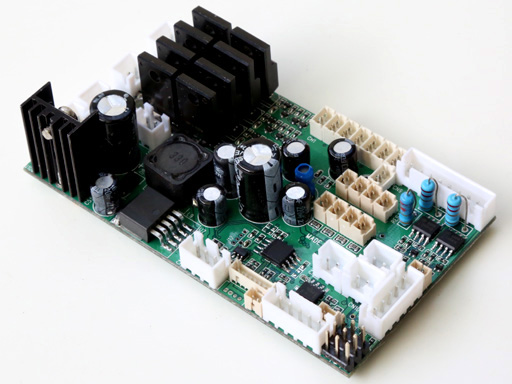
MFK01 Series RC
Tractor Controller |
MFK01,
an integrated RC car controller,
for
upgrading TAMIYA RC Tractor into
proportional radio control
with Light and Sound Effect
Overview

-
MFK01 series controller uses 2.4G, 10-Ch S.BUS RC system to control R/C truck forward/backward movement, turning,
gear change and coupler
-
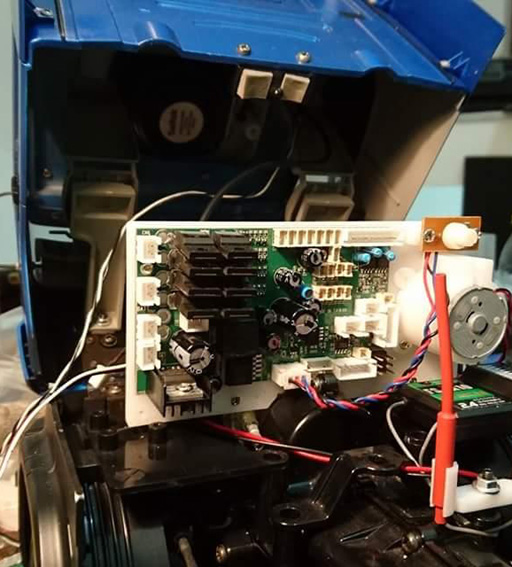
Miniature design allowed your to
keep interior of
diver cabin
-
Ultrasonic ESC Propulsion motor driver
-
22KHz, 8-bit high quality sound with digital sound mixer
-
15W
Class-A audio amplifier
-
0.8A BEC
-
Support
vibrate motor support
-
Wide operating voltage rage, from 7.2 to 12V, support 3S
Li-Po battery
-
Safety shutoff prevents unwanted movement while signal lost
-
Auto R/C signal detection
-
V2 Smoker driver
Reference of installation to
keep interior of
diver cabin
Terminology
Ultrasonic
ESC is the ESC block which switch FET at ultrasonic speed, make motor
rotation very smooth and quite.
V2
Smoker driver smoker fan/compressor speed is proportional to
engine RPM and Load
Class-A audio amplifier widely used in high fidelity amplifier market
due to their absence of crossover distortion and reduced odd-harmonic and
high-order harmonic distortion.
Variants
|
|
MFK01 |
|
Remote Control
system
|
2.4G RC system with S.BUS |
|
User
software
Programmability |
YES |
|
User Sound
Programmability
|
YES |
|
Engine Sound Simulation
|
V2
|
|
Motor driver Current
|
Standard:60A |
|
Audio Amplifier |
15W @ 7.2V~12V |
|
Head Lamp |
YES |
|
Head Lamp Flasher |
YES |
|
Fog Lamp |
YES |
|
Roof Light |
YES |
|
Hazard flasher |
YES |
|
Left/Right Blinker |
YES |
|
Speed Indicator
Lights |
YES |
|
Reverse Light |
YES |
|
Break
Light |
YES |
|
Proportional
Smoker driver |
V2
proportional to engine
RPM
and Load |
|
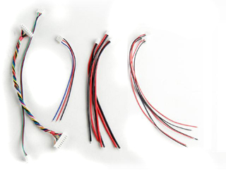
Kit contained |
MFK01 board *1, S.BUS cable*1,
LED Cable*10
|
|
Reference Price |
200
150* |
*Promotion price
Product
Identification System
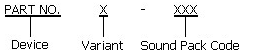
| Device |
MFK01 |
MFK01 series
RC tractor controller |
| |
|
|
|
Variant |
Blank |
Standard |
| |
S |
Support S.BUS
interface |
| |
P |
Sound
Programmable |
| |
|
|
|
Sound Pack |
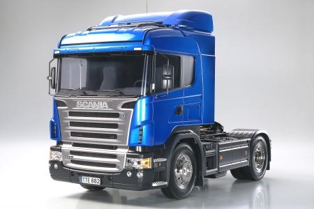
R470 |
Scania R470 |
| |
..... |
Refer to TK Sound Pack webpage for more
information |
Hardware Variants
|
Variant Code |
Description/Notice/Change/New
Features |
Release Schedule |
|
- |
Standard Specification, 20/60A track current.
15Watt Class-A audio amplifier
|
Released |
|
|
|
|
|
|
|
|
Software Revisions
|
Software
Package
Name |
Description/Notice/Change/New
Features |
Release Schedule |
|
V1 |
-10-CH
S.BUS control scheme,
- Ultrasonic
ESC for
Propulsion
Motor
- Ver.2 Bootloader
- V2 Smoke driver, proportional
to engine RPM and engine loading |
Released |
|
|
|
|
Boot loader Revisions
Boot Loader is a application, executed in TK
board, to handles software update, sound pack programming and setting data
update
|
Version |
Description/Notice/Change/New Features |
Release Schedule |
|
Ver.2
|
-Auto Sound pack change detection
-Auto Clean at software update |
Released |
Pre-built sound packss
|
Sound Pack Code
|
Model
|
Release Schedule
/sound pack file |
|
R470_V1 |
Scania R470 version 1 |
Released
Download |
|
R470_V2 |
Scania R470 version 1 |
Released
Download |
*Please write to distributor or us for decompression password
Ordering Information
|
Item No. |
Kit
Contained |
Price (USD) |
|
MFK01SP |
MFK01 board *1, S.BUS cable*1,
LED Cable*10
|
150 |
Accessories
|
Part Number
|
Description
|
|
Configuration IR REMOTE |
For
Tank Personalization function |
|
IR005 |
Std. IR battle
emitter kit |
|
IR010 |
High
Power IR battle
emitter kit |
|
CAB001 |
1.25mm pitch cable
connector for connecting IR LED or Gun Flash LED |
|
HL Cable Set |
Motor
Cable *2
Battery Cable *1
Speaker Cable *1
Smoke Unit Cable *1,
Smoke Unit Switch Cable (no
switch) *1
8P Inter-connection Cable *1
Volume Control Cable( no VR ) *1
 |
|
HL Power
Cable |
One end to TK20, another end to
battery, one switch in the middle
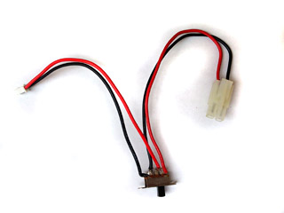 |
|
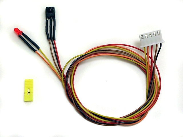
IR Programming Line |
5P connector with IR receiver
& Red LED indicator, and a 2.54mm-pitch Jumper

|
10-CH
S.BUS
mode
control
scheme
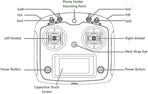
Transmitter: FS-i6S, self-centering VrA
and VrB type Radio
RX:FS-iA10B
Receiver connection table
|
Receiver |
Connection |
|
CH1 |
Not connected
空接 |
|
CH2 |
Not connected
空接
|
|
CH3 |
Coupler and
Motorized
support leg servo
連結器及支撐腳舵機 |
|
CH4 |
Gear select servo
換檔舵機 |
|
CH5 |
Not connected
空接 |
|
CH6 |
Not connected
空接 |
|
CH7 |
Not connected
空接 |
|
CH8 |
Not connected
空接 |
|
CH9 |
Not connected
空接 |
|
CH10 |
MFK01 CH8 |
|
i.Bus SERVO |
MFK01 S.BUS port(J7) |
|
i.Bus SENS |
Not connected
空接 |
|
Layout
操作方式 |
Command
指令 |
S.BUS
Channel
assignment
S.BUS
各通道設置 |
|
  |
Steering Left and Right
轉向舵機左右轉 |
CH1 (Stick)
通道1(撥桿) |
|
 |
Stick
Up: Throttle of propulsion
motor(CN6)
撥桿向上: 行走馬達(CN6)
油門
Stick Dw: Propulsion
motor (CN6)
Break
撥桿向下:
行走馬達(CN6)煞車
|
CH2 (Stick)
通道2(撥桿) |
|
|
Coupler and
Motorized
support leg
連結器舵機左右擺動 |
CH3
(Stick)
通道3(撥桿) |
|
|
Gear Select
換檔舵機左右擺動 |
CH4
(Stick)
通道4(撥桿) |
|
SwA
開關A |
Up: Forward Gear
撥桿向上:前進檔
Dw:
Reverse Gear
撥桿向下:倒退檔 |
Assign SwA to CH5
開關A設置到通道5 |
|
SwB: Up
SwC: Center -> Up
開關B:向上
開關C:
置中 -> 向上 |
Natural Gear Shift In/Out
(Safety switch for
Propulsion motor driver
)
空檔(行走馬達解鎖)
|
Assign SwB to CH7
Assign SwC to CH8
開關B設置到通道7
開關C設置到通道8 |
|
SwB: UP
SwC: Center -> Down
開關B:向上
開關C:
置中 -> 向下
|
Engine start/stop
引擎音效啟動 |
Assign SwB to CH7
Assign SwC to CH8
開關B設置到通道7
開關C設置到通道8 |
|
SwB: Center
SwC: Center -> Up
開關B:置中
開關C:
置中 -> 向上
|
Aux Light(L3) On/Off
輔助燈(L3)開關 |
Assign SwB to CH7
Assign SwC to CH8
開關B設置到通道7
開關C設置到通道8 |
|
SwB: Center
SwC: Center -> Down
開關B:置中
開關C:
置中 -> 向下
|
Hazard
flasher/Parking lamps On/Off
警示燈.駐車燈開關(左右方向燈同時閃爍) |
Assign SwB to CH7
Assign SwC to CH8
開關B設置到通道7
開關C設置到通道8 |
|
SwB: Down
SwC: Center -> UP
開關B:向下
開關C:
置中 -> 向上 |
Controlled Switch(L4) on/ff,
can used to control
-
Rotating Light Unit On/Off
- Motor
- LEDs
控制開關(L4)開關,
可用於連接
-迴轉燈模組
-馬達
-發光LED
|
Assign SwB to CH7
Assign
SwC to CH8
開關B設置到通道7
開關C設置到通道8 |
|
SwB: Down
SwC: Center -> Down
開關B:向下
開關C:
置中 -> 向下 |
Roof Light(L2) On -> Head Light On
-> Fog Light On -> Lights Off
車室燈(L2)
->頭燈開 ->霧燈開 ->全關 |
Assign SwB to CH7
Assign SwC to CH8
開關B設置到通道7
開關C設置到通道8 |
|
SwD
開關D |
UP: VrA
in Mode 1
DW: VrA in
Mode 2
撥桿向上:轉輪A置於模式1
撥桿向下:轉輪A置於模式2
|
Assign SwD to CH6
開關A設置到通道6 |
|
VrA
轉輪A |
Mode
1:
-
UP:
Right Blinker
-
Down:
Left Blinker
Mode
2:
模式
1:
模式
2:
-
轉輪往上: 輔助電變(CN7)正轉
-
轉輪往下: 輔助電變(CN7)逆轉
|
Assign VrA to CH9
轉輪A設置到通道9 |
|
VrB
轉輪B |
Up: flashing high beam(L1)
or turn off high beam
Up for 5 seconds:
keep
high beam on
Down:
Horn
轉輪往上: 閃遠光燈或關閉遠光燈
轉輪往上五秒:遠光燈保持開啟
轉輪往下:
喇叭
|
Assign VrB to CH10
轉輪B設置到通道10 |
|
Parameter
|
|
Unit
|
|
Maximum current of
Propulsion
Motor
ESC |
60 |
A |
|
Maximum current of
Propulsion
Motor
ESC, A1 Hardware |
105 |
A |
|
Maximum current of turret and
cannon elevation ESC |
7 |
A |
|
Maximum current of Smoker Driver |
7 |
A |
|
Maximum supply
voltage |
12 |
V |
|
Minimum supply
voltage |
7.2 |
V |
|
On-board audio amplifier
Maximum power (
Battery= 7.2V) |
15 |
W |
MFK series connector and pin assignments
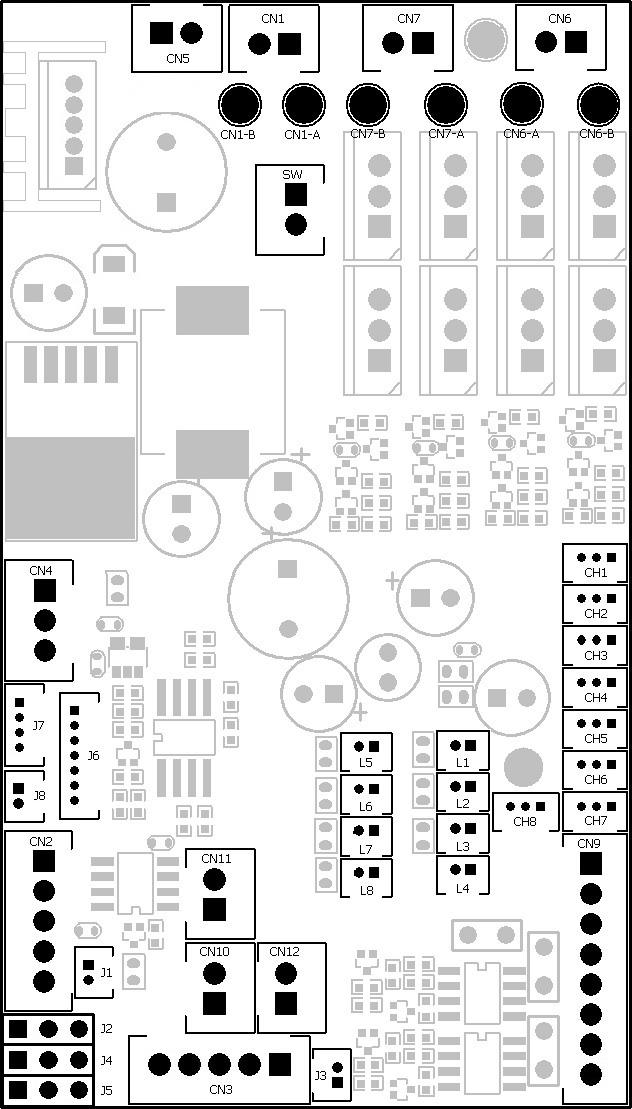
|
Connector
|
Description
|
Note |
|
SW |
Switch Cable Port |
Connect to switch cable
|
|
CH1
|
CH1 control
signal
通道1信號
|
NA |
|
CH2
|
CH2 control
signal
通道2信號
|
NA |
|
CH3 |
CH3 control
signal
通道3信號 |
NA |
|
CH4
|
CH4 control
signal
通道4信號
|
NA |
|
CH5 |
CH5 control
signal
通道5信號 |
NA |
|
CH6 |
CH6 control
signal
通道6信號 |
NA |
|
CH7 |
CH7 control
signal
通道7信號 |
NA |
|
CH8 |
CH8 control
signal
通道8信號 |
Connect
to receiver CH8 to power Receiver
1. Receiver Signal( White Wire)
2.
Receiver + ( Red Wire)
3. Receiver - ( Black Wire)
連接到接收機,
無功能, 僅供電給接收機用 |
|
CN1
|
Battery Power
電池接口
|
1. Battery +
2.
Battery -
|
|
CN2 |
IR Configuration
Port
紅外設置接口 |
1.
IR receiver +
2.
IR receiver SIG
3.
IR receiver -
4.
IR Configuration Indicator
LED -
5. IR
Configuration Indicator
LED + |
|
CN3 |
NA |
|
|
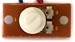
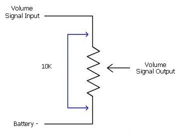
CN4 |
Sound
Volume
音量控制 |
1.
Volume Signal
Output (
Wiper pin of VR
)
2. Battery -( 1 outside pin of
VR )
3.
Volume
Signal
Input (
1 outside pin of VR )
 |
|
CN5 |
Speaker
喇叭 |
|
|
CN6
(*2/2) |
Propulsion
Motor
行走馬達
|
|
|
CN6-A |
Propulsion
Motor
Additional Pad
行走馬達焊點
|
When 540 or 550 Motor is used
for track driving, use this pad to connect motor |
|
CN6-B |
Propulsion
Motor
Additional Pad
行走馬達焊點
|
When 540 or 550 Motor is used
for track driving, use this pad to connect motor |
|
CN7
(x/1) |
Aux ESC
輔助電變 |
Aux ESC, can be used to
control winch motor |
|
CN7-A |
Aux ESC
Additional Pad
輔助電變焊點 |
When 540 or 550 Motor is used, use this pad to connect motor |
|
CN7-B |
Aux ESC
Additional Pad
輔助電變焊點 |
When 540 or 550 Motor is used, use this pad to connect motor |
|
CN9 |
Light
Effect Functions
燈光功能 |
1. Left blinker LED-
2. Right blinker LED-
3. Left blinker, Right blinker,
Engine Vibration
Motor +
4.
Engine Vibration
Motor
-
5. HEAD Light LED -
6. HEAD Light LED +
7. FOG Light LED +
8. FOG Light LED -
1. 左方向燈 LED-
2. 右方向燈 LED-
3. 左方向燈, 右方向燈r,
引擎振動馬達+
4.
引擎振動馬達
-
5. 頭燈
LED -
6.
頭燈 LED +
7. 霧燈
Light LED +
8.
霧燈
Light LED -
|
|
CN10
(*3/0) |
Smoke
Unit /
Smoke
Unit Fan
發煙器 |
1.
Smoke Unit + / Smoke Unit Fan +
2.
Smoke Unit - / Smoke Unit Fan -
|
|
CN11 |
Smoke
Unit /
Smoke
Unit Fan switch
發煙器開關 |
1.
Switch
2.
Switch
|
|
CN12 |
Smoke
Unit Heater
發煙器加熱器
|
1.
Smoke
Unit Heater +
2.
Smoke
Unit Heater - |
|
J1 |
N/A
無
|
1. Not connected
2. Not connected |
|
J2
(5/5) |
Steering servo port
轉向舵機
|
1. Battery - (Black Wire)
2.
+5V ( Red Wire)
3. Signal( White Wire) |
|
J3 |
Break Light Port /
Boot loader Indicator
煞車燈/開機狀態燈 |
To Work
with
LED
Main Gun Flasher(F003)
1. LED +
2. LED - |
|
J4
(*1/4) |
N/A
無
|
|
|
J5
(*3/3) |
N/A
無
|
|
|
J6 |
Programming Port
燒錄音效接口 |
To connect TK Programmer |
|
J7 |
S.BUS port
S.BUS接口 |
To connect
S.Bus Receiver
1. +5V
2.
Battery -
3.
S.BUS RX
4. Not connected |
|
J8 |
NA
|
|
|
L1 |
Headlamp flasher
遠光燈
|
1. LED +
2. LED - |
|
L2 |
Roof Light
車室燈
|
1. LED +
2. LED - |
|
L3 |
Aux Light
輔助燈 |
1. LED +
2. LED - |
|
L4 |
Controlled Switch on/ff
輔助開關 |
When connect to a
Rotating Light/Motor:
1. -->Rotating Light Unit/ Motor +
2. -->Rotating Light Unit/Motor -
When connect to a
LED:
1. --> 200ohm in-serial resistor --> LED +
2. --> LED - |
|
L5 |
Reverse Light
倒車燈
|
1. LED +
2. LED - |
|
L6 |
Speed Indicator LED1
速度指示燈1
|
1. LED +
2. LED - |
|
L7 |
Speed Indicator LED2
速度指示燈2
|
1. LED +
2. LED - |
|
L8 |
Speed Indicator LED3
速度指示燈3
|
1. LED +
2. LED - |
Installation Guide
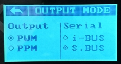
S.BUS setup
Transmitter:
1.Turn on Transmitter i6s and enter setting
function, go to system->output mode, set Serial to S.BUS
2. Enter aux channel setup, set
channel 5 to SwA, channel 6 to SwD, channel 7 to SwB, channel 8 to SwC, channel
9 to VrA and channel 10 to VrB
3.
Go to system->stick mode, then set to M1 mode
4. Go to end points page, set end point to
100% for every channel.
Receiver and control board:
1. Plug connector with S.BUS
label on it into S.BUS port on receiver.
Personalization
Settings
of MFK series board can be set by
cconfiguration IR remote and programming line(
as follow)
 Steps
to set parameters:
Steps
to set parameters:
STEP 1: Turn power off,
plug programming line
to CN2,
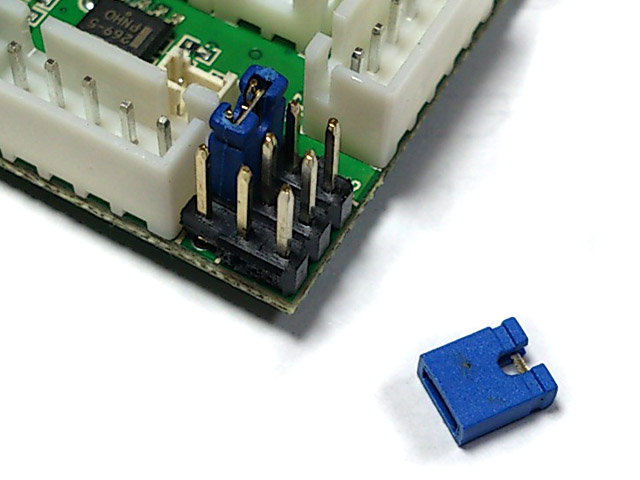
STEP 2: Install a jumper to J2
as shown below, turn power on,
STEP 3: Point
Configuration IR remote to
programming line
receiver,
refer to function table listed below and press the button
of function that you want to set,
STEP 4: Indicator
of programming line flashes according to
the setting value.
STEP 5: turn power off, remove
jumper on J2, then power on and you are set.
Function tables:
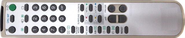
Function Page Selection:
Press "-/--" Key on IR Configuration Remote to select. for
TK22G2 only
|
Available Settings |
Indicator
flashes times |
Description |
|
Select
settings on Page 1 |
1* |
TK board
goes back to this page after power on |
|
Select settings on Page 2
|
2 |
|
|
Select settings on Page 3
|
3 |
|
|
Select settings on Page 4 |
4 |
|
*Text in black means that
setting function is on page1.
Function Page 1
Save
current setting to
PRESET 1: Press number
key "1" on TV remote to save,
|
Available Settings |
Indicator
flashes times |
Description |
|
Save to
PRESET 1 |
1 |
Indicator flashes when setting
is saved
|
Save
current setting to PRESET 2: Press number
key "2" on TV remote to save,
|
Available Settings |
Indicator
flashes times |
Description |
|
Save to
PRESET
2 |
2 |
Indicator flashes when setting
is saved
|
*Once
you've adjusted everything, you can
push "1" or
"2" to save
current setting to PRESET 1
or 2. If you don't do this saving the board remembers
the last settings.
Use saved settings:
Press "ENT" or "SOUND MODE" Key on TV remote to select.
|
Available Settings |
Indicator
flashes times |
Description |
|
Use
PRESET 1
setting |
1 |
|
|
Use
PRESET 2 setting |
2 |
|
|
Use Factory Default Setting
( Read-Only ) |
3 |
To
restore factory
default value in case of setting data is messed up. |
*To
switch between the presets you press either "sound
mode" or "enter" button, once the preset is selected,
switch tank off and remove setup jumper. Switch back on and away you
go.
Momentum effect On/Off: Press "SLEEP(0x36)"
or " "
on TV remote to select "
on TV remote to select
|
Available Settings |
Indicator
flashes times |
Description |
|
Off |
1* |
|
|
ON |
2 |
|
Function Page 2
Aux ESC Sound Mode:
press
"SOUND Mode" Key on IR
Configuration Remote to select
|
Available Settings |
Indicator
flashes times |
Description |
|
Standalone device |
1 |
Device controlled by
Aux ESC is standalone device, not powered by engine, has dedicated
sound effect |
|
Powered by Engine |
2* |
Device controlled by
Aux ESC is powered by engine,
and load engine as
device moves forward.
such as actuator for tipper/dump
truck beds. |
Function Page 3
Ultrasonic ESC
start voltage increase:
Select page 3, press
"3" on IR Configuration Remote to increase level,
indicator flash once each time, indicator flash twice when reach maximum level
Ultrasonic ESC
start voltage decrease:
Select page 3 , press
"6" on IR Configuration Remote to decrease level,
indicator flash once each time, indicator flash twice when reach minimun level
Ultrasonic ESC start voltage reset to zero:
Select page 3, press
"DISPLAY" Key on IR
Configuration Remote to reset start voltage,
indicator flash once every time.
Evaluation sample::
Function Page 4
16K ESC
start voltage increase:
Select page 4 , press
"VOL UP" on IR Configuration Remote to increase level,
indicator flash once each time, indicator flash twice when reach maximum level
16K ESC
start voltage decrease:
Select page 4 , press
"VOL Down" on IR Configuration Remote to decrease level,
indicator flash once each time, indicator flash twice when reach minimun level
16K
ESC start voltage reset to zero:
Select page 4, press
"MUTE" Key on IR
Configuration Remote to reset start voltage,
indicator flash once every time.
|