|
|
|
Conversion Part List:
Part Number Annotation in instructions: <A1>: conversion kit part number (A1) : DML M4A3E8 Kit part number
|
|
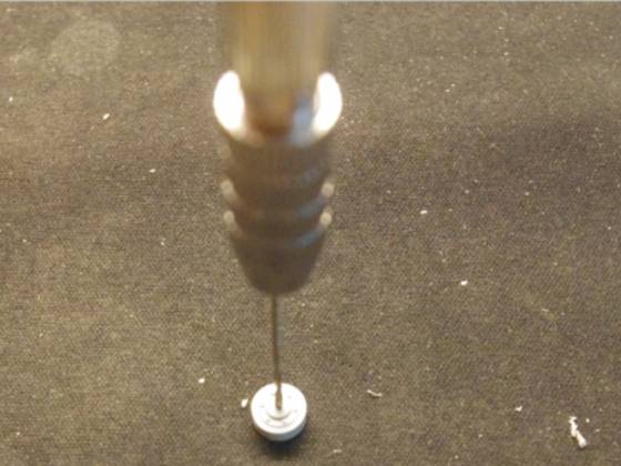
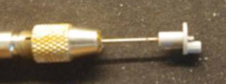
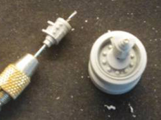
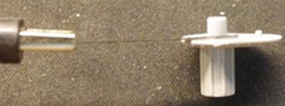
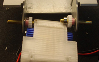
Support roller Make 1.3mm hole on the center of (D7)
Make 0.8mm hole on the shaft for support roller(Q7)
Bolt (D7) with 1.2mm*6 screw
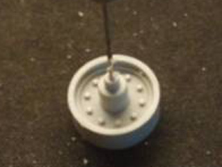
Make 0.8mm hole on the shaft for support roller(Q22)(Q21)
Make 2mm hole on the center of (Q22)
Fit Q21 to shaft and then bolt 1.2mm*10 screw
Glue (Q22) to (Q21) with cement
|
|
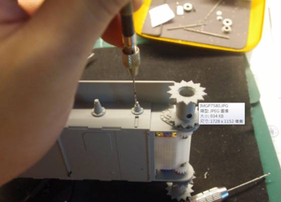
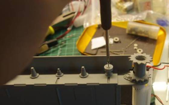
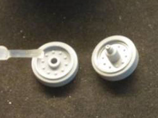
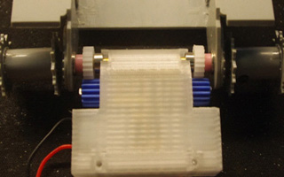
Return roller Make 1.0mm hole on (Q31)
Make 1.3mm hole on (Q25)
Bolt (Q25) to (Q31)
Make 1.0mm hole on (Q27), glue (Q27) to (A1)
Adjust track tension and then fasten (Q31),
Glue (Q26) to (Q25)
|
|
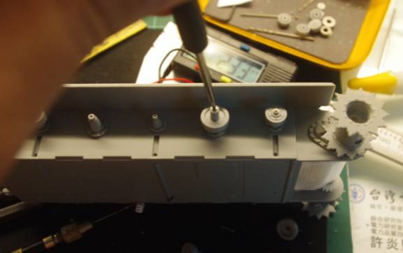
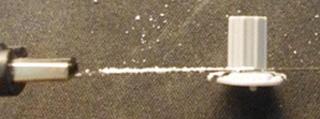
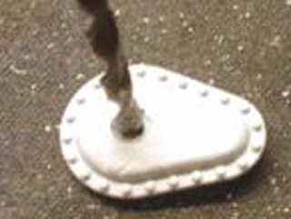
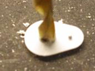
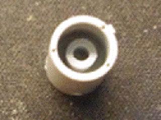
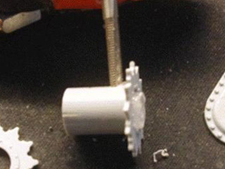
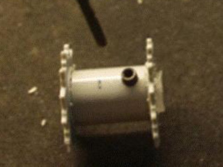
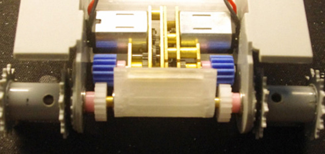
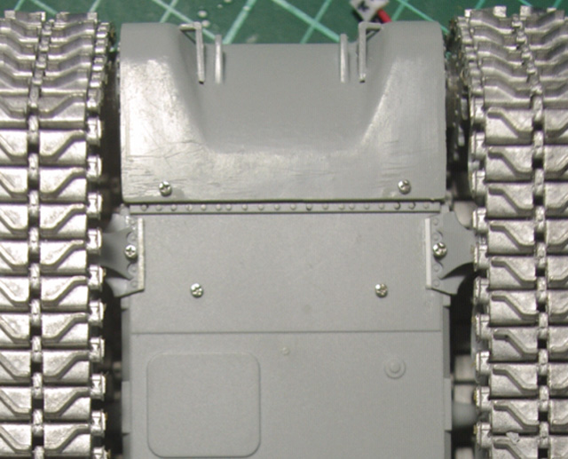
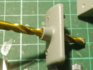
Transmission Remove shaft on (Q24)
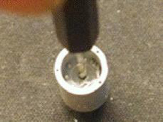
Make 6mm hole on (Q24) for driving shaft, use smaller drill to find center first, then use larger one to finish.
Glue modified (Q24) to chassis
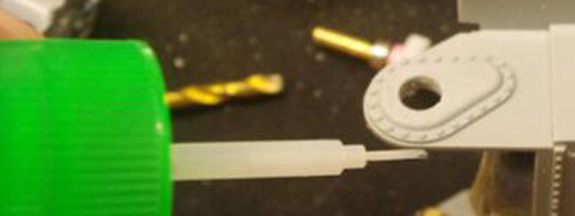
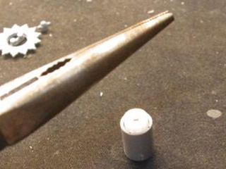
Remove tube shape portion on (Q23) by center drill, the make it through by 3mm center drill
Push 3mm Driving Shaft Cap<A7> into modified (Q23)
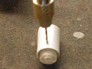
Drill through (Q23) and <A7> by 1mm and then 2.5mm drill bit , tap 2.5mm hole with (M3*0.5) screw tap
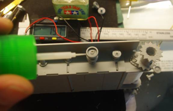
Fit hex socket set screw temporally,
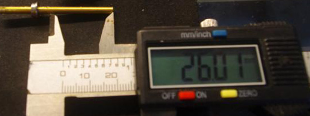
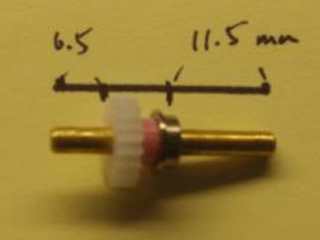
Cut brass 3mm Driving Shaft into 26mm in length
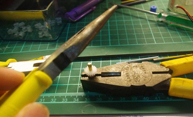
Push final gear into driving shaft in depth of 6.5mm
Insert spacer<A2> and lip type ball bearing <A4>
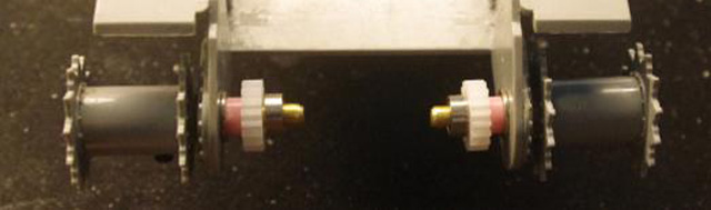
Insert final gear assembly to modified Q24, fit another ball bearing to shaft, fit driving sprocket.
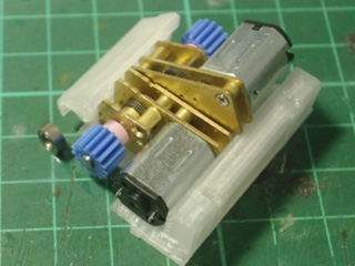
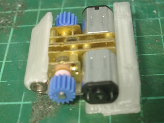
-Insert driving shaft spacer<A2, Pink> to the shaft of geared motor<A1>, fit blue gear<A2> to the shaft of geared motor<A1>, solder cable to geared motor, fit geared motor to Geared Motor Housing Lower Cover<A5>
Insert bearing on final gear shaft to Geared Motor Housing Lower Cover<A5>,
Bolt upper motor cover
Bolt front armor with <A8> and <A5> to chasis
|
|
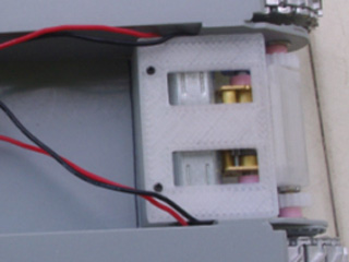
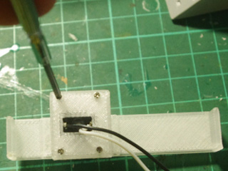
Back Panel Bolt switch and Volume control VR to <D3>
Wire 2P cable to switch, then plug to SW port on TK35, Wire 3P cable to Volume control VR, then plug to CN4 port on TK35 Wire 2P cable to speaker, then plug to CN5 port on TK35 Wire 3P charge port to another 3P port, then plug to battery
Fit back panel assembly and fasten with screw
glue two magnet on (C19) part
|
|
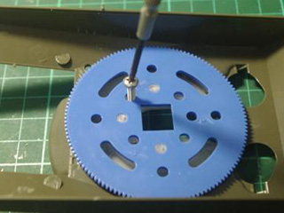
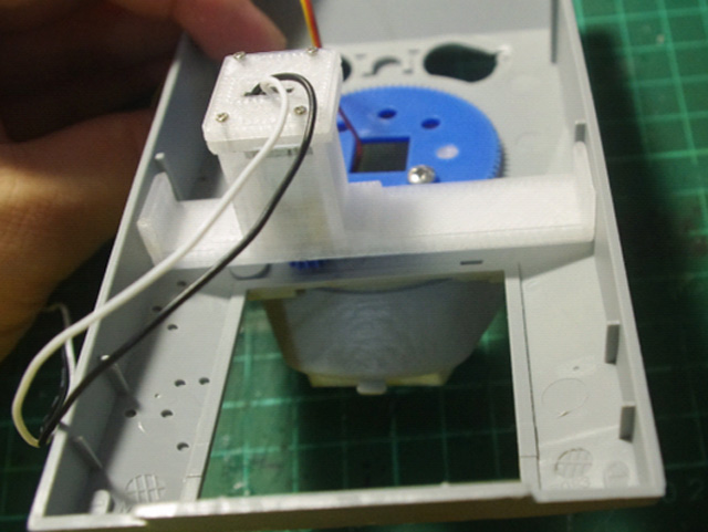
Turret Put 2 nuts on Turret Gear fixture<E5> top side, bolt gear from bottom side
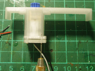
Re-drill 1mm hole on<E3>, push D-Shaft blue Gear <E2> into turret rotate geared motor shaft<E1>, insert geared motor into geared motor housing<E3>, solder cable to geared motor, then bolt back cover
Glue housing<E3> to upper hull,
Wire 2P cable to switch, then plug to SW port on TK35, Wire 3P cable to Volume control VR, then plug to CN4 port on TK35 Wire 2P cable to speaker, then plug to CN5 port on TK35 Wire 3P charge port to another 3P port, then plug to battery
Fit back panel assembly and fasten with screw
glue two magnet on (C19) part
|
|
TK35 Control Board Installation Fit TK35 holder<E8> with screw<????>
Fit TK35 on holder with screw
|
|
Machine Gun Drill through with 1mm drill
insert light guide(
Install MG as instruction manual
Glue MG Breech<G7>
to (F3), wire 2P cable to
3mm, white-light LED, put LED in holder
and then plug cable to
|
|
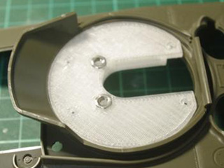
Turret rotation Put on upper hull
Put turret washer<F6> on upper hull
Fit (F5) and then turret gear
Fit <F4> on <F5>
Fit turret front amour panel and machine gun as instruction manual
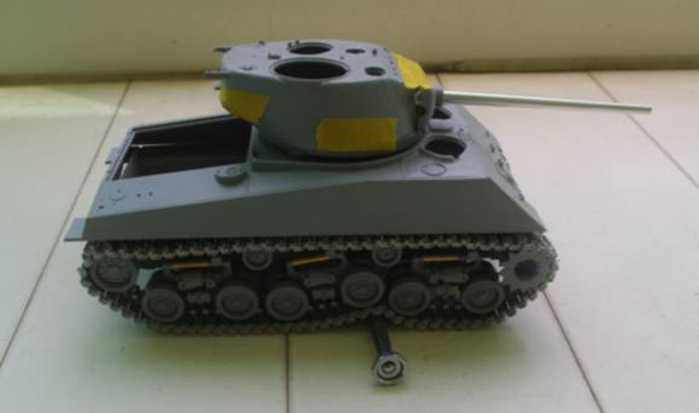
Fit and glue 1.5mm thickness magnet<G Bag> to the hole pointed by YELLOW arrow<G6>, 2.5mm thickness magnet<G Bag> to the hole pointed by RED arrow Apply glue to the surface that will contact upper turret hull.
fit upper turret hull to proper position before glue is cured
turret hull can be removed when super glue is cured
Fit
D-Shaft Gear<F3> to geared motor<F2>, wire 2-P cable to motor lead and
then plug cable to
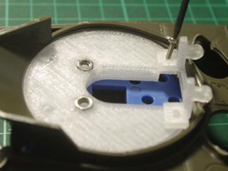
Put two nuts on turret motor assembly and bolt motor assembly from the bottom
bolt slip ring<F10> with Screw<???>
Fit turret motor assembly to tank chassis upper hull
make sure turret gear can be driven smoothly
Glue turret motor assembly to tank chassis upper hull by super glue; also glue four magnets to four holes on turret motor assembly.
Glue four magnets to four holes on upper hull fixture<F8>
fit to turret motor assembly; apply super glue on the bottom and fit to tank chassis lower hull before glue is cured.
when glue is cured, make 1.5mm hole and bolt it
The way to fit upper turret hull
|
|
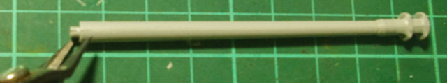
Main Gun、GUN ELEVATE、Gun Elevation、Machine gun Bolt the gun carriage<F3> to lower turret floor (E5),
Drill (B7) with
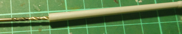
Cut gun barrel
Drill gun barrel with 2mm drill bit
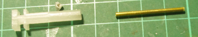
Fit <F5> to <F4>
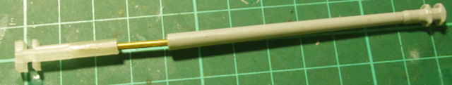
Fit <F5> to modified gun barrel
Insert <G3> to gun breech<G2>
Fit gun breech<G2> to gun mantlet(D12), not glue is required, glue gun barrel to gun barrel recoil adaptor<G3>
Bolt main gun to gun carriage with screw<???>
Fit recoil servo<G1> to gun breech
Make 0.8mm hole and bolt it with M1.0 screw, plug servo cable to J2 on TK35 Insert slip ring cable to cable guide opening Solder SMD white light LED for main gun flash, and connect to J3 on TK35 Like main gun, drill thought machine gun barrel, insert light guide
Make hole on gun breech,
Bolt MG breech to main gun breech
Bolt M1.2*7 screw to elevation servo arm
Bolt
elevation
Bolt
|
|
Make 1.0mm hole on turret floor and bolt etched prototyping board<D3> on it.
Wire all positive node together, such as main gun LED J3 (+),machine gun LED CN9-1(+),IR LED_CN2-2(+) Wire all 5V node together, such as barrel recoil servo (+),gun elevation servo J4(+),IR battle receiver CN2-1(+), Wire all ground node together, such as barrel recoil servo (-),gun elevation servo J4(-),IR battle receiver CN2-1(-).
|