|
|||||||||||||
|
|||||||||||||
|
Part List:
Part Number Annotation in instructions: <A1>: conversion kit part number
|
|
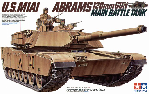
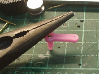
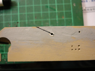
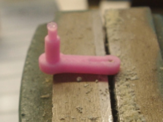
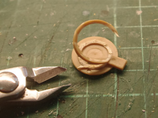
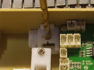
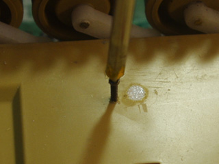
Torsion Adjustable Suspension Drill shaft hold for suspension arm by 0.5mm ( to find the center) and than 1.5mm drilll
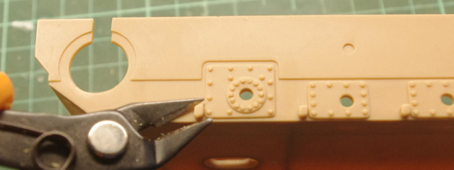
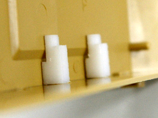
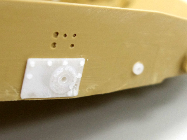
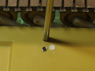
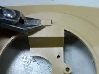
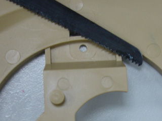
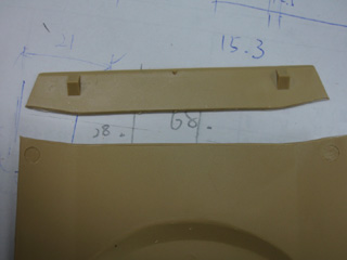
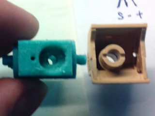
For TAMIYA M1, Ground off suspension arm and texture on side panel as picture below.
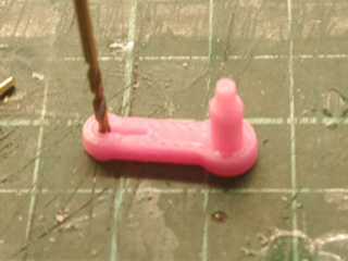
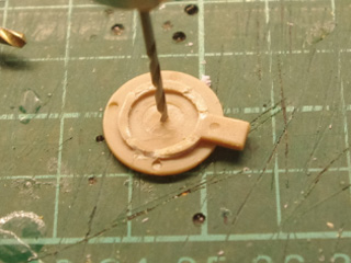
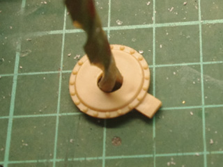
then to expand shaft hold to 3.2mm with 3.2mm drill
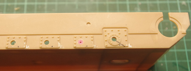
For Trumpeter M1, just need to remove the pin and expand shaft hold to 3.2mm
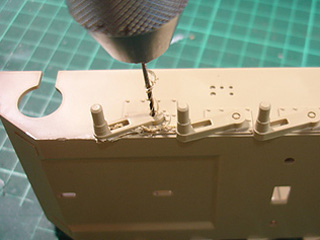
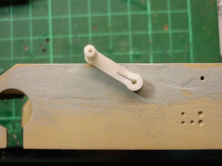
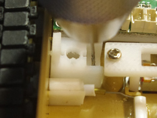
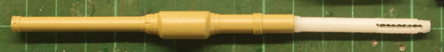
Trim inner shaft part with 1.5mm drill
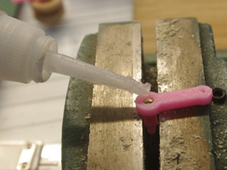
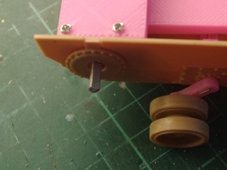
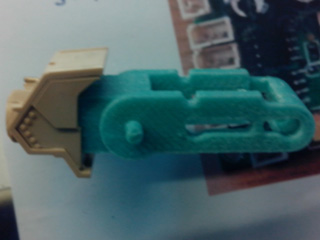
Insert shaft part to shaft hold and glue it to lower hull
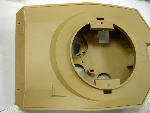
From different view angle
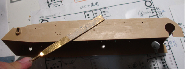
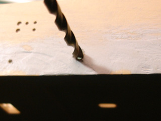
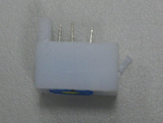
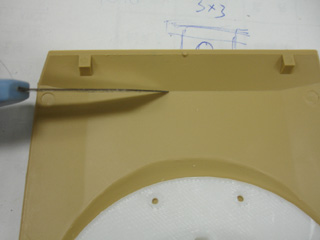
For TAMIYA M1, also install outer panel
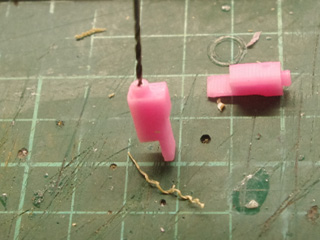
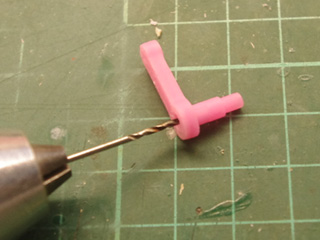
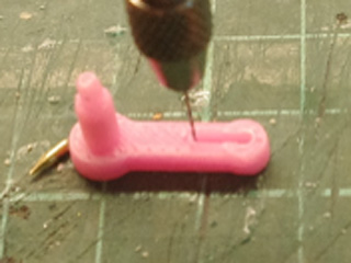
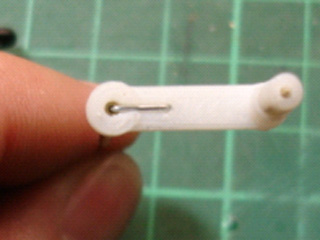
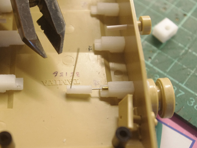
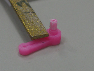
Drill suspension arm part with 1.4mm drill, suspension part is made of ABS, much strange than original part.
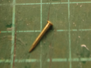
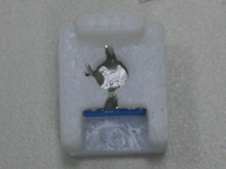
Push a pin to the hold just drilled, cut pin that exceed shaft
Glue it
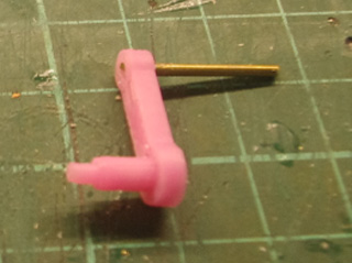
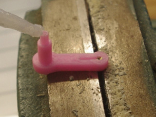
Expand hold on suspension arm part to 1.5mm(left) and 0.5mm(right)
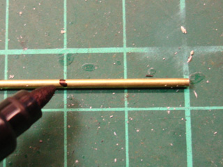
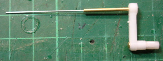
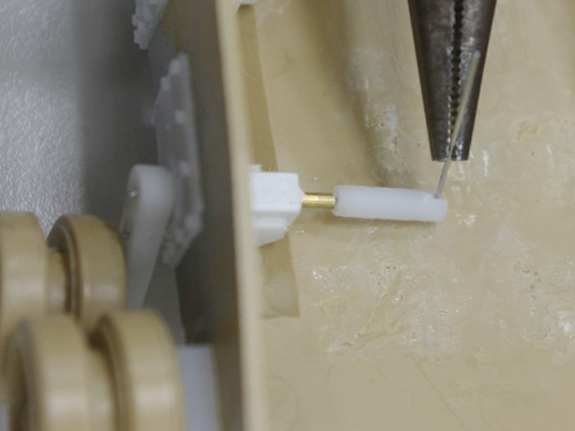
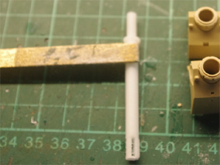
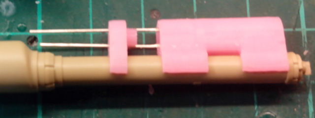
Cut copper tube into length of 20mm and trim the opening a bit
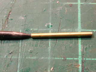
fit copper tube and glue it
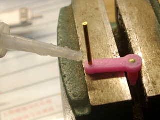
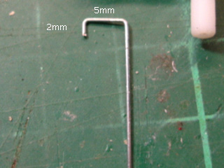
Bend spring wire with tweezers and fit to suspension arm
Finished suspension arm. use 0.5mm diameter spring wire for 1st, 6th and 7th suspension arm, 0.4mm for 2nd, 3rd, 4th and 5th suspension arm.
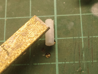
Smoothen the surface of plastic tube for spring wire
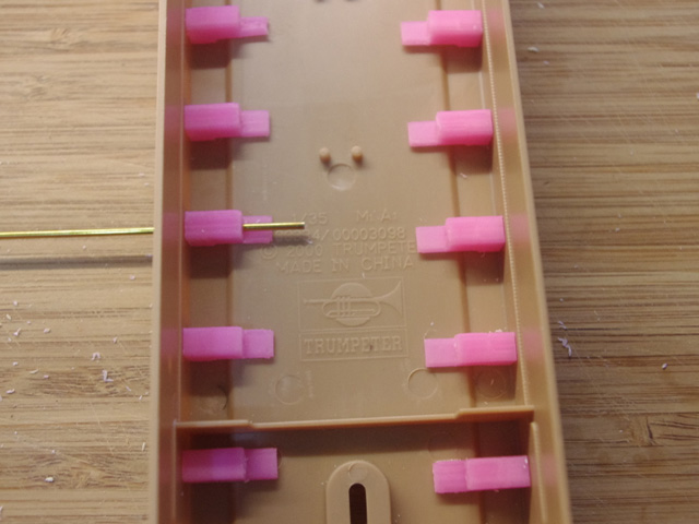
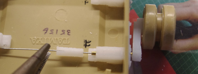
Insert spring wire through shaft hole on side panel
Bend spring wire into the slot on plastic tube
Shorten spring wire.
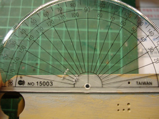
Use protractor to set angle of each suspension arm 1st and 7th to 30~35 degree, 2nd to 6th to 25~30 degree 1
fasten torsion bar by hex socket cap screws
Do the same to all suspension arms
|
|
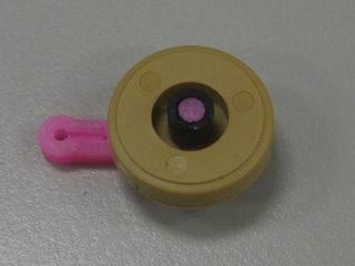
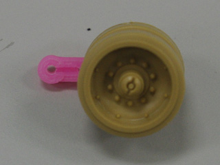
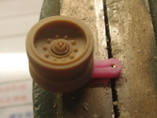
Road Wheel For TAMIYA Kit, polish road wheel shaft a bit, put fit (B2), rubber tube, glue rubber tube to shaft,
then fit (B3)
For trumpeter kit, set suspension arm shaft vertically, fit road wheel, put a drop of quick glue on the top of shaft,
the fit hub to shaft
|
|
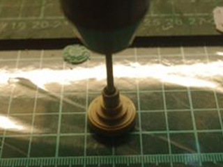
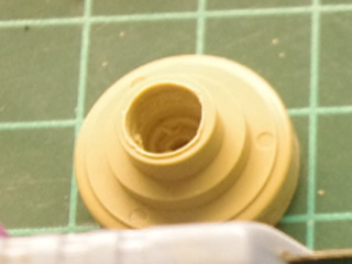
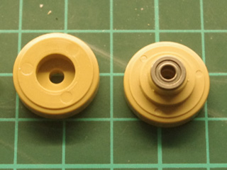
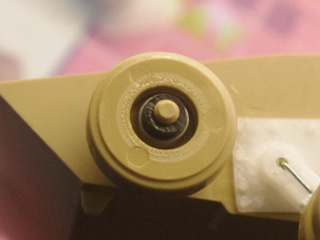
Return Roller Expand axel to 6mm
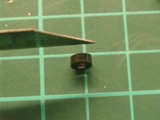
fit 6mm ball bearing, cut rubber cap into half
fit to shaft, glue rubber cap to shaft, and cement iroad wheel
|
|
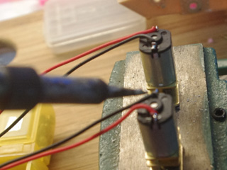
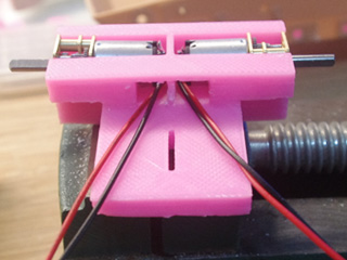
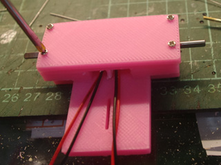
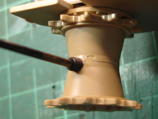
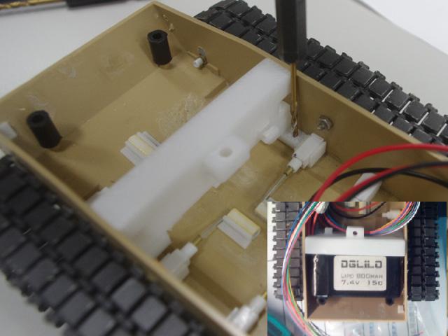
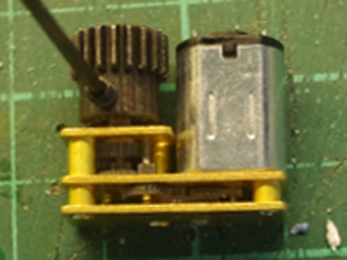
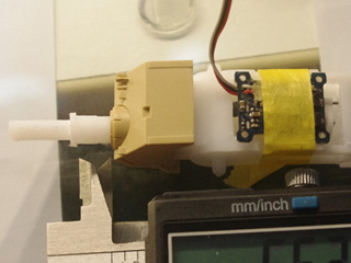
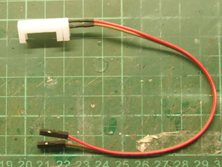
Power Pack Solder cable to motor terminal
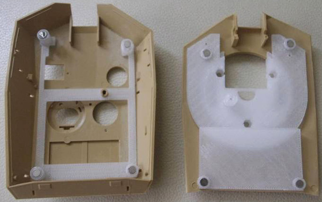
Fit motor to Gear Motor Housing Lower Hull<A2>
Bolt upper cover<A3>
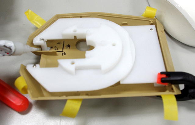
Bolt power pack assembly to chassis from bottom, track tension can be adjusted by the position of power pack
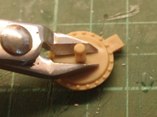
Modify hub
Then glue to chassis,
|
|
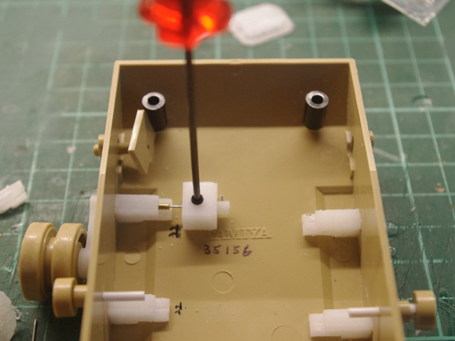
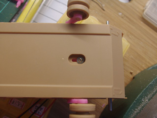
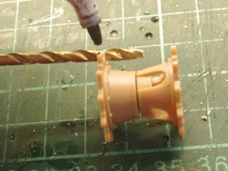
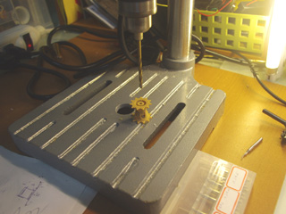
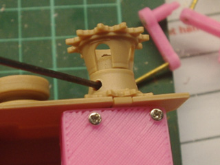
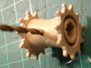
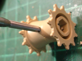
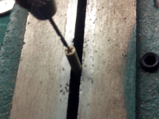
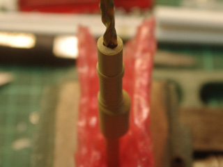
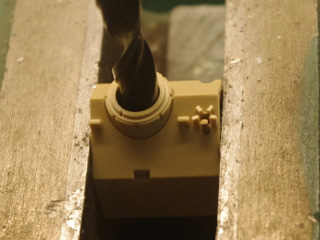
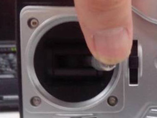
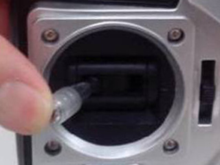
Driving Sprocket For Trumpeter kit, first to mark drilling depth on 3mm drill bit, then use drill table to drill.
Drill(1mm then 2mm) and tap(3mm*0.5) sprocket
fit sprocket by hex socket cap screw
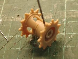
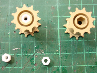
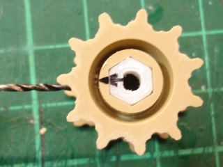
For TAMIYA kit, first to fit Hex cap to socket
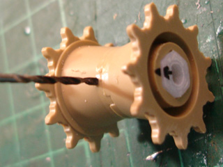
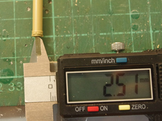
use 1mm drill bit to find center
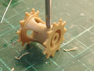
expand to 2.5mm by 2.5mm drill bit, then tap(3m*0.5) it
fit sprocket by hex socket cap screw
|
|
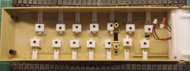
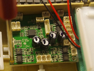
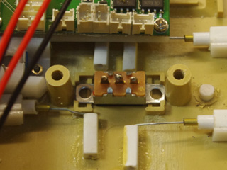
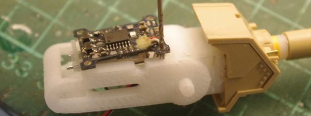
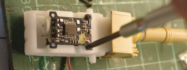
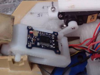
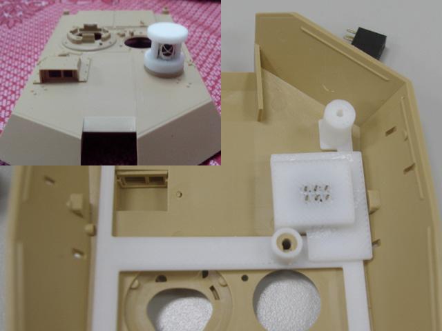
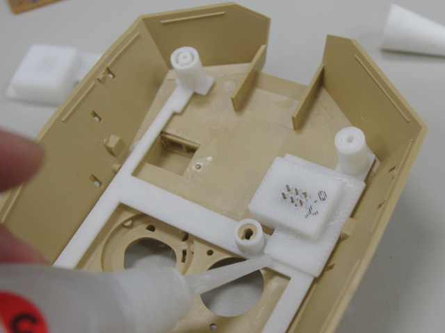
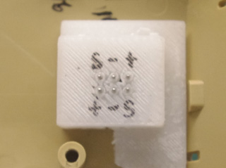
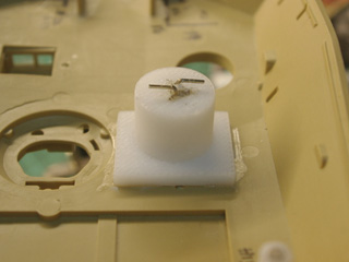
Electronics in tank hull installation Bolt TK35 board to TK35 fixture<D10> then glue to chassis
Put Volume
control fixture<D7> on chassis and make 3mm and 1.6 mm hole
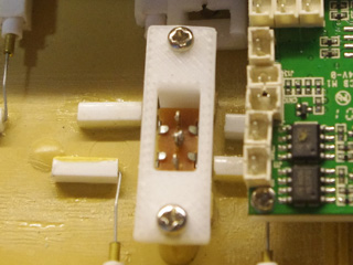
Fit Volume control to fixture
Blot fixture and volume control, then adjust volume by screw driver
Put Switch<D4> and fix it with switch fixture <D5> and bolt.
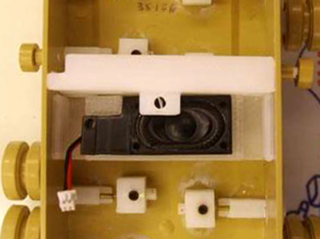
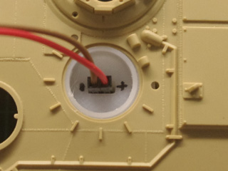
Drill hole then bolt battery fixture<D8>from bottom
Fit speaker next to battery fixture
|
|
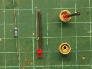
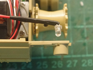
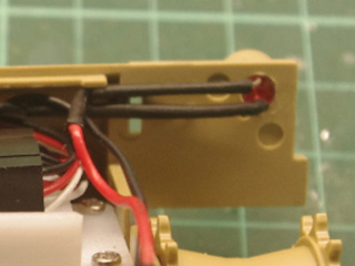
Lighting Tail light, first to wire in-series 150ohm resistor to LED
Make 3mm hole then fit tail light led.
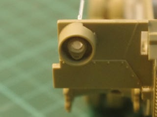
Headlight , first to remove some
coating on enamel-insulated wire
make hole on headlight part, insert LED assembly to headlight part
insert wire to upper hull
solder enamel-insulated wire to 2-P cable
|
|
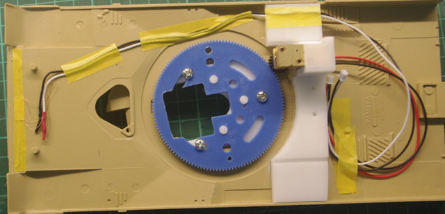
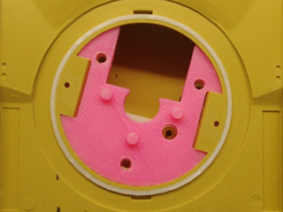
Turret Rotation Modify turret parts as following
become this
Cut off tail section of lower turret tail, glue to upper turret hull
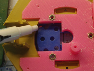
Glue magnet to upper turret support frame( Left ) and inner turret floor (Right), Put some drop of quick glue between upper turret support frame and upper turret, fit upper turret assembly to lower turret, adjust turret support frame to make sure up and lower turret fit perfectly before quick glue is cured.
When quick glue is cured, open lower turret, apply more quick glue to strengthen the bound.
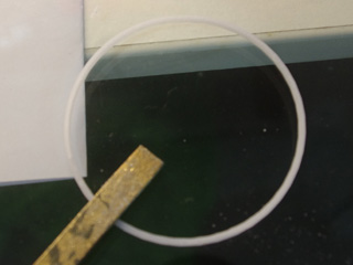
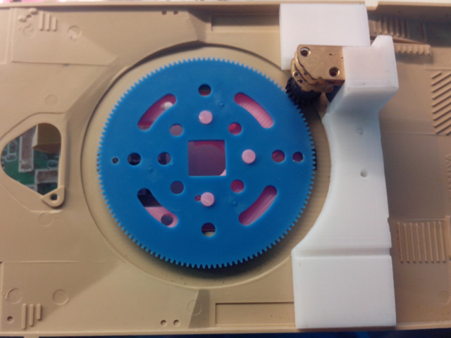
grind the ring part then fit to turret ring
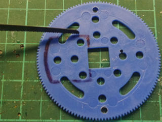
fit blue gear to turret floor, mark the opening on turret floor, make same opening on blue gear
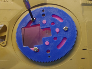
Blot blue gear on turret floor
fasten black gear on the shaft of geared motor by hex socket cap screws, the fit assembly to housing<E3>
Glue housing<E3> to upper hull
|
|
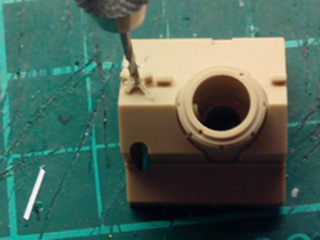
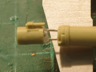
Main Gun Drill hole for MG light guide
fit gun breech to gun mantle
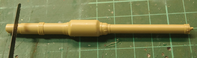
Remove tail portion of gun barrel
Drill gun barrel by 4mm drill bit
Fit Gun barrel recoil adaptor<F3> to gun barrel
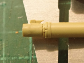
Drill gun mantle according outer diameter of gun barrel
grind
Gun
barrel recoil adaptor<F3> if it can not move smoothly when it's inserted
into
gun breech
Insert recoil servo arm into the slot on Gun barrel recoil adaptor tail and fit recoil motor on top of gun breech
Make 0.8mm hole on gun breech
the bolt servo recoil in the top right, bottom left and right corner
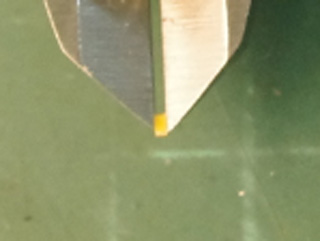
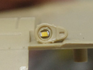
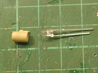
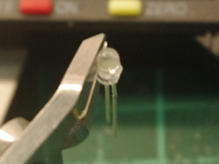
Make 3mm hole on the center of muzzle for LED, make 2.5mm hole on gun barrel front end for LED leads
Trim off the lip on LED bubble
Insert muzzle assembly
|
|
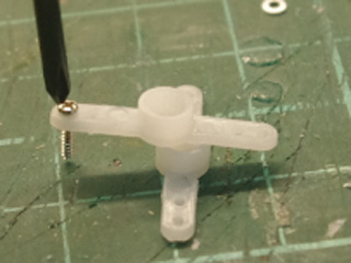
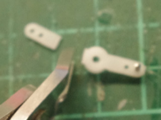
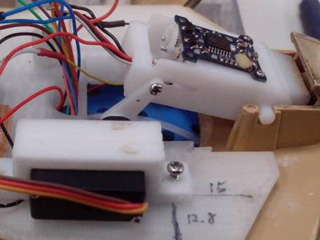
Elevation Fit a screw on servo arm, trim servo arm
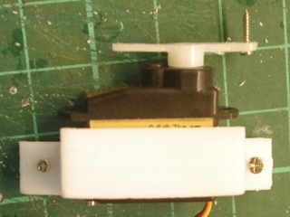
Fit servo to servo fixture<F9> and bolt it
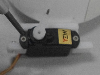
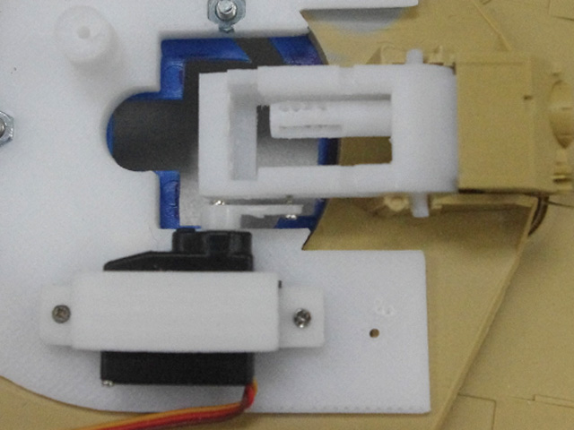
Bolt elevation assembly to turret floor
Adjust servo arm angle till gun barrel can be depress to -10 degree and left to +20 degreer
can be left to +20 degree then bolt servo arm
|
|
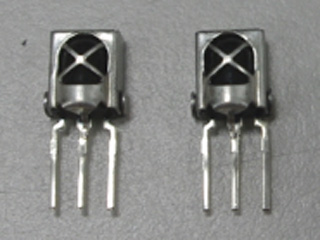
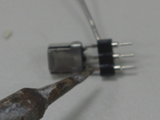
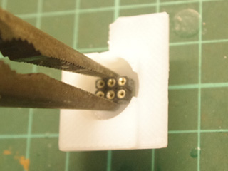
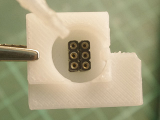
IR receiver (Optional ) Trim IRM lead to 13mm,
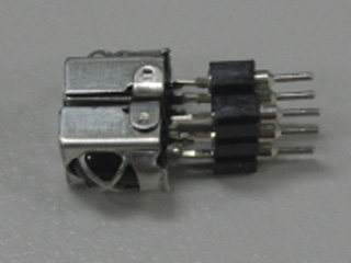
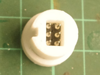
Solder IRM to socket
Insert IRM assembly to IR battle unit housing
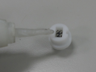
Glue IRM assembly and upper cover
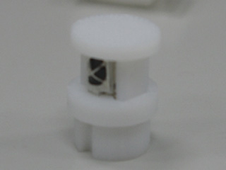
Fit socket to IR battle base and glue it
Fit IR battle base so that IR battle unit can be plugged smoothly
Glue IR battle base
Pin assignment for wiring, S stands for HBU/TBU SIG on CN2-1 of TK35, - for HBU/TBU - and + for HBU/TBU +
|
|
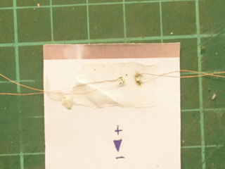
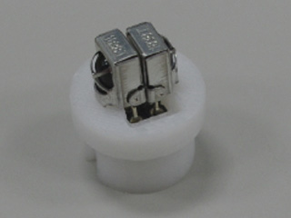
IR battle transmitter Insert IR emitter LED in to IR battle transmitter housing
Solder cable to IR transmitter LED
Similar to IR battle base, insert socket then glue it
So that you can hook and remove IR transmitter easily.
All modification are done, refer to TK35 web page to do wiring.
|
)