|
|
|
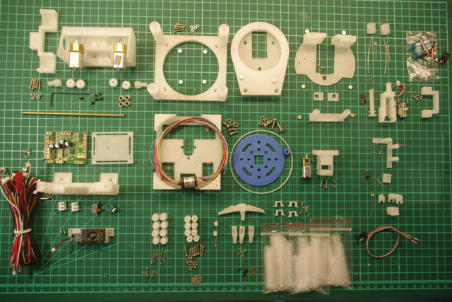
Part List:
Part Number Annotation in instructions: <A1>: conversion kit part number (A1) : 38(t) Kit part number
|
|
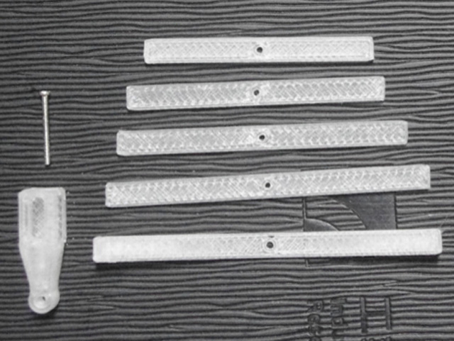
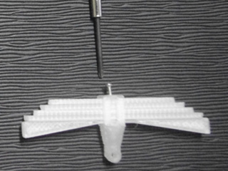
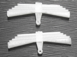
Suspension Spring <B Bag>
Fit stacked spring panel<B1> to <B3> with 1.2mm * 10mm screw<B3>, make 4 units
|
|
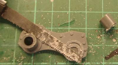
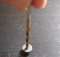
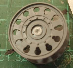
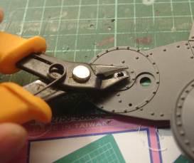
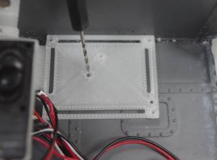
Road wheel Suspension Arm
Modify G2 and G3 part, first to remove road
wheel shaft
grind machine mark
Drill 1.5mm hole at center
Trim here a bit to avoid interference when road wheel is running
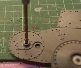
than to modify G13 part, first to remove hallow shaft
Drill 1.0mm hole at center
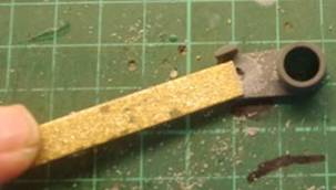
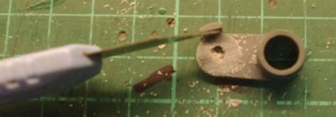
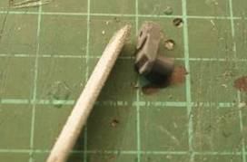
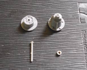
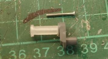
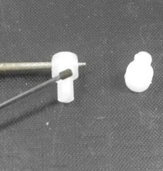
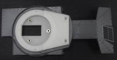
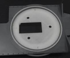
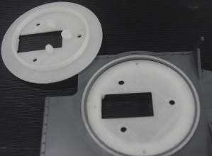
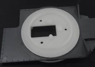
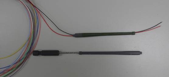
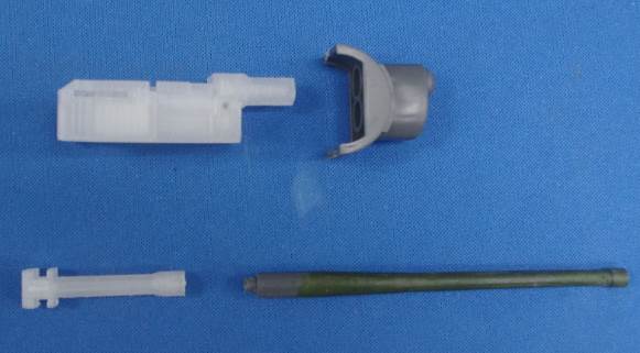
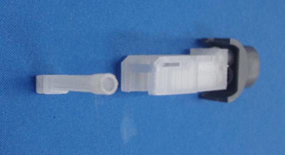
Modify (F5) part, to cut shaft off and grind machine mark
find center point by 2.5 mm drill bit and drill 1.2mm hole at center
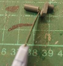
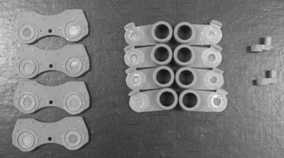
This picture shows all modified parts
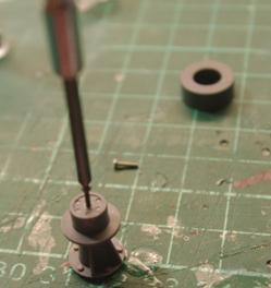
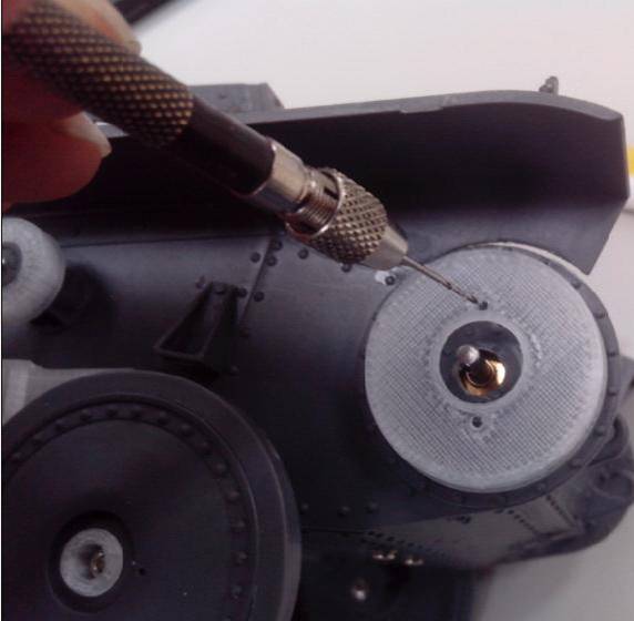
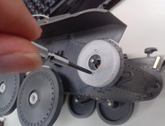
Install T shaft< C1 > to (G13), first to drill a hole on (G13),
Insert (G2/G3) to T shaft with screw and net
Make 0.8mm hole
Install flat panel spring assembly with screw and washer
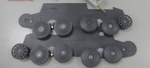
Fit road wheels
Do not miss washer
|
|
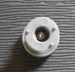
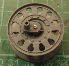
Supporting Wheel Drill 3mm hole( 2mm depth ) on back side of G14,
Drill through (G14) and (G16) with
then drill thought (G16) with 1.3mm drill,
fit it with screw and nut<????> on the back of (G14)
|
|
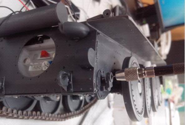
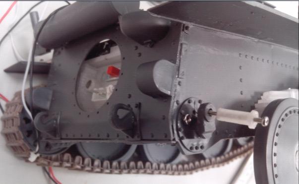
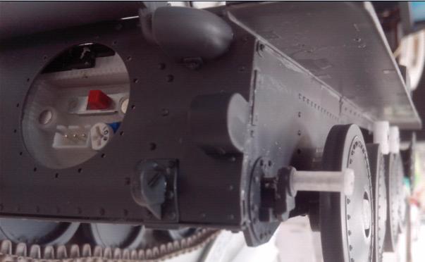
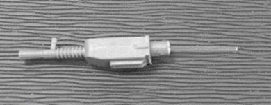
Idler Fit idler shaft <C5> and <C6> with screw
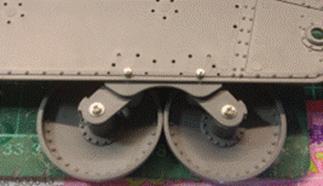
Completed road wheel and idler
|
|
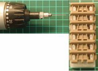
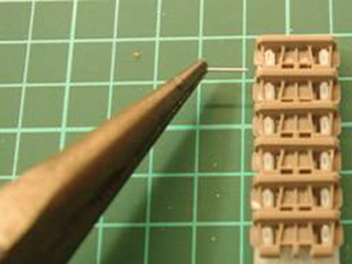
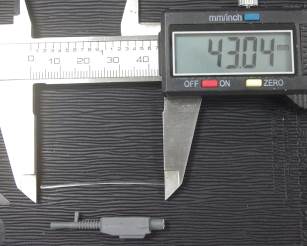
Track Link Fit track block on fixture, drill thought it with 0.8mm drill, then insert 0.6mm in diameter, 12mm in length steel wire.
Shorten plastic track pin by 1/3 and then fit to track block with cement( Hint: use T shape pin on outside, none T shape pin on inside), each track link is made of 91~93 track block
|
|
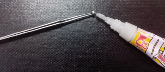
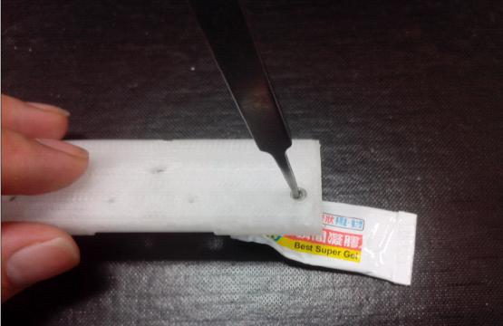
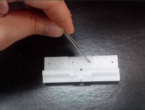
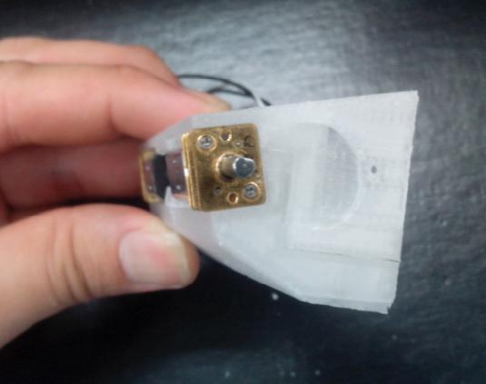
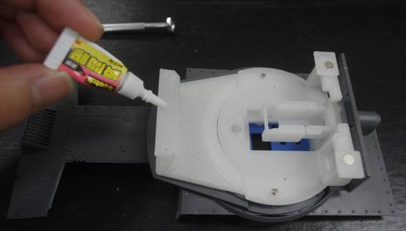
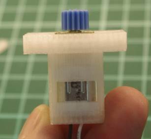
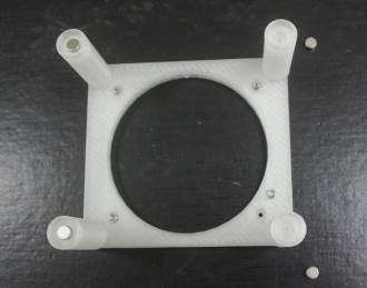
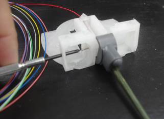
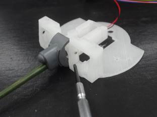
Gearbox Apply glue to M2 nut
Fit M2 nut to motor housing<A1> before glue is cured
Bolt upper cover<A2>
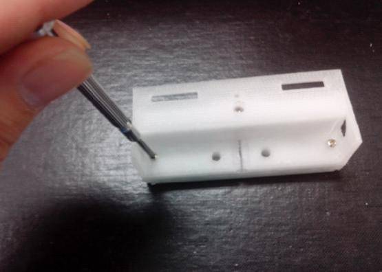
Tap the hole in front of upper cover<A2>
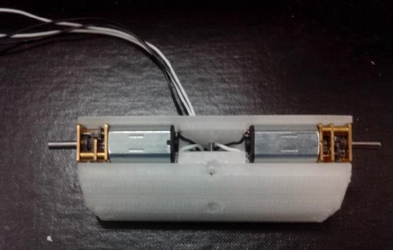
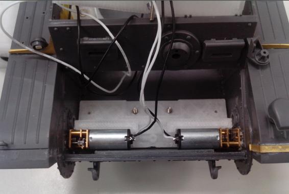
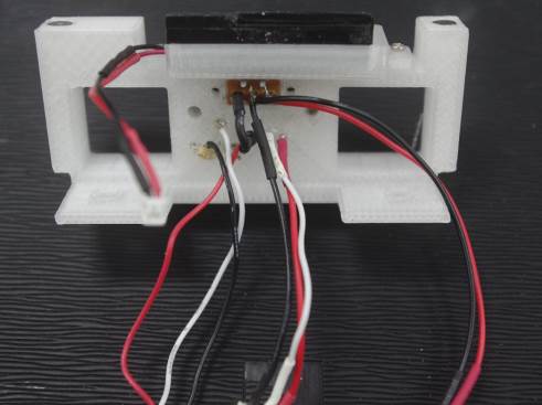
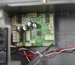
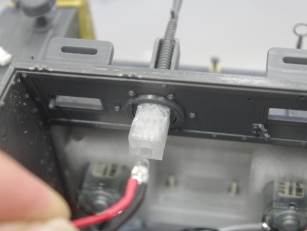
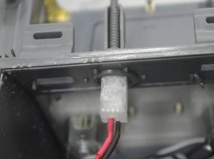
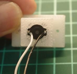
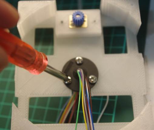
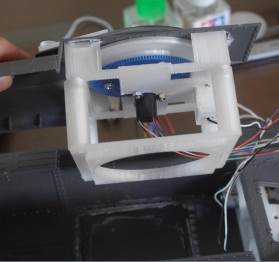
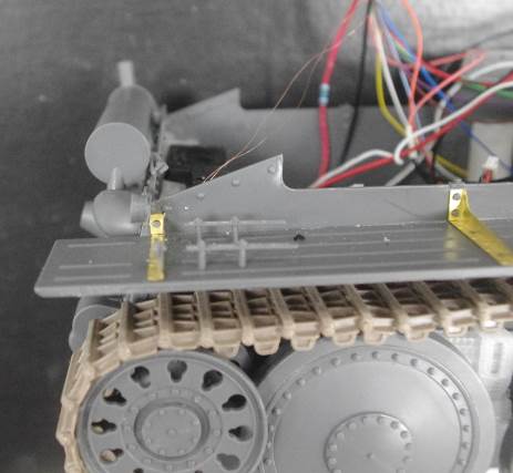
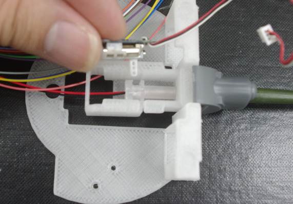
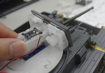
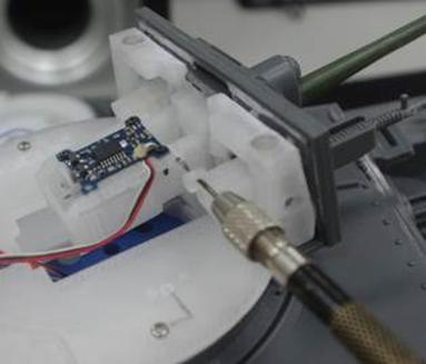
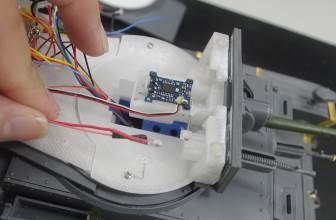
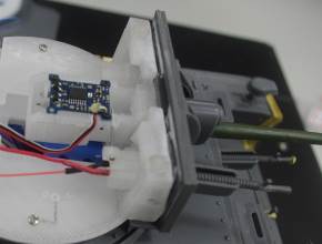
Solder cable to geared motor and fit to housing, left cables as shown in picture
Wire cable and test it, then connect to CN6、CN7 port on TK35 control boar
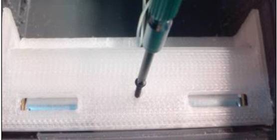
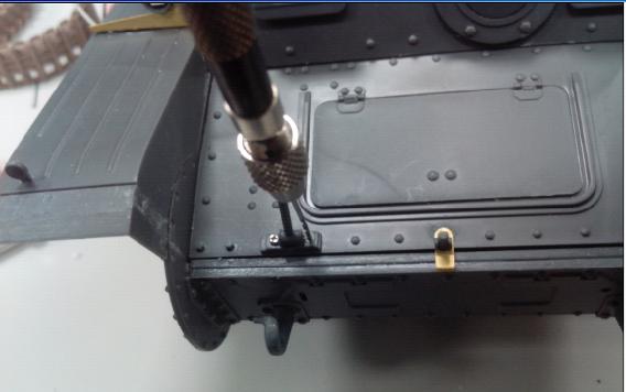
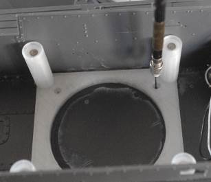
Blot motor housing from the bottom
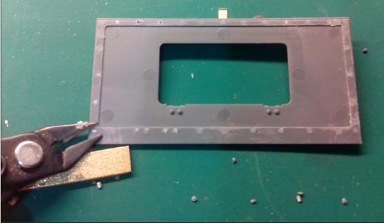
Remove texture on from upper hull armor panel
Make 1mm hole
Bolt it with screw<???>
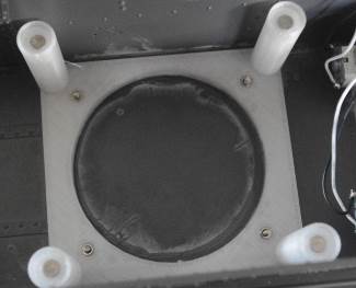
Cut PE part
So that you can access maintain transmitter unit
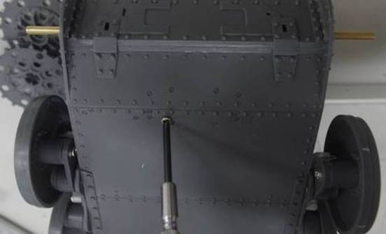
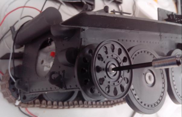
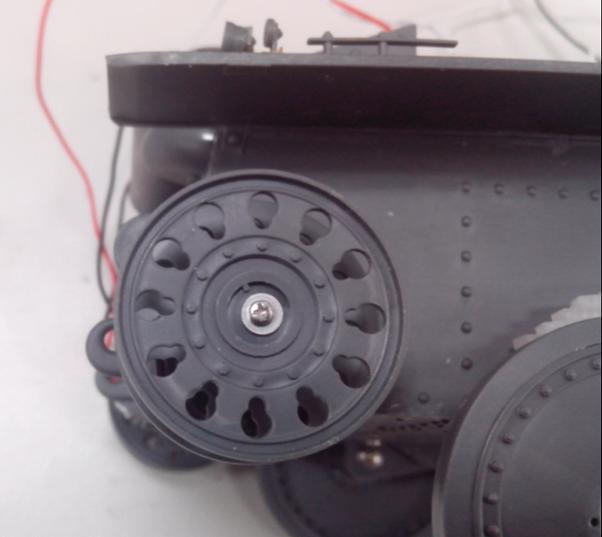
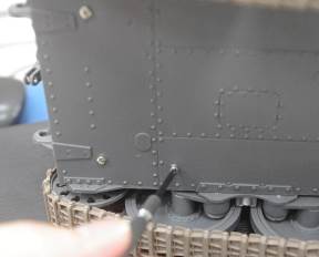
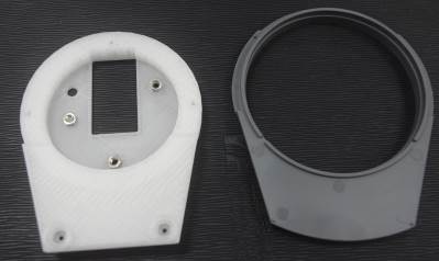
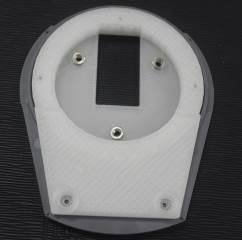
Remove shaft on (B2) and (B11) part, than make 5mm hole for driving shaft
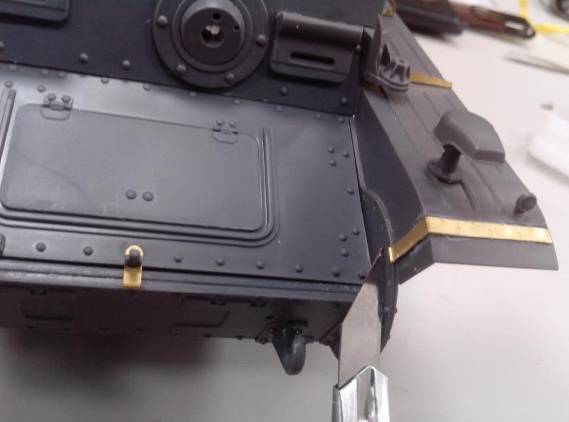
Make 1mm hole on side panel through hub<A5>
Bolt driving sprocket hub to side panel
Tap(M3*0.5) driving shaft cap<A4> and fit hex socket set screw<A4 Bag>
Fit driving shaft cap to driving sprocket
Bolt driving sprocket from the opening on the hub
Fit track and adjust idler to set track tension
Remove idler and make 1.5mm hole on side panel
Install idler
|
|
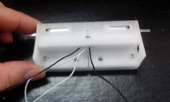
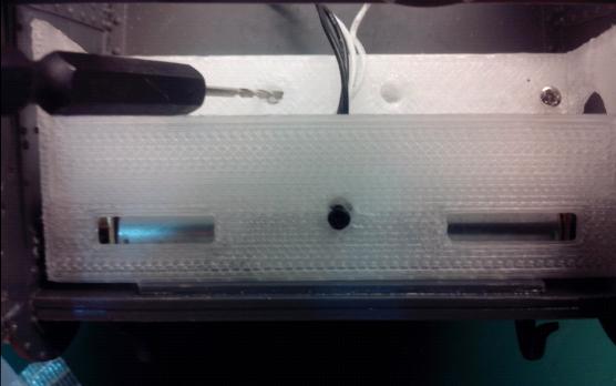
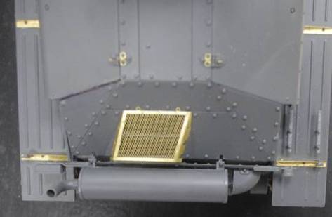
Back Panel
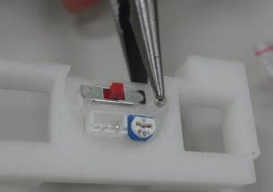
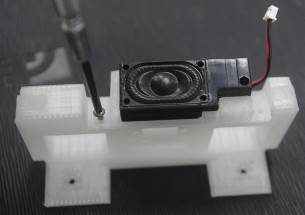
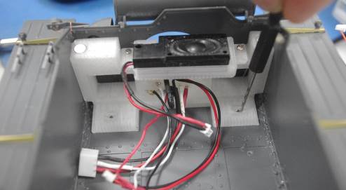
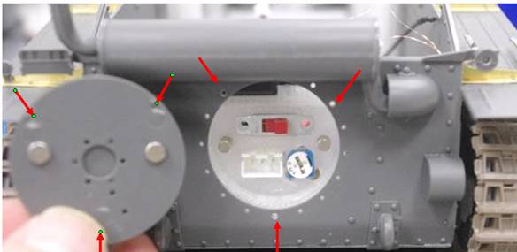
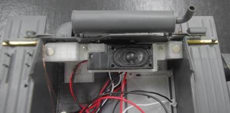
Fit switch, Volume control VR、3P charge port, magnet and speaker(E1~E10) on Tail Parts Fixture<E4>
Wire 2P cable to switch, then plug to SW port on TK35, Wire 3P cable to Volume control VR, then plug to CN4 port on TK35 Wire 2P cable to speaker, then plug to CN5 port on TK35 Wire 3P charge port to another 3P port, then plug to battery
Fit back panel assembly and fasten with screw
glue two magnet on (C19) part
|
|
TK35 Control Board Installation Fit TK35 holder<E8> with screw<????>
Fit TK35 on holder with screw
|
|
Machine Gun Drill through with 1mm drill
insert light guide(
Install MG as instruction manual
Glue MG Breech<G7> to (F3), wire 2P
cable to 3mm, white-light LED, put LED in
holder and then plug cable to
|
|
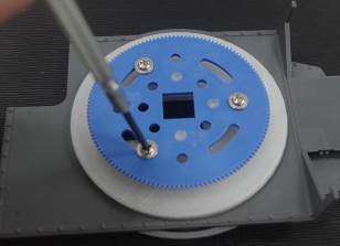
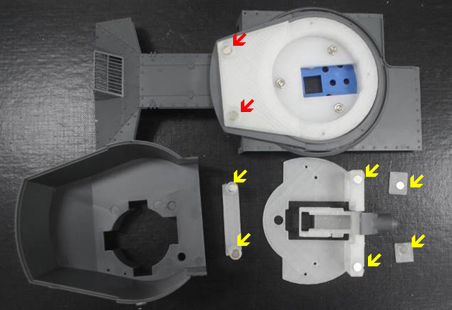
Turret rotation
Fit lower turret hull <F7>
to (C17) Put on upper hull
Put turret washer<F6> on upper hull
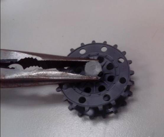
Fit (F5) and then turret gear
Fit <F4> on <F5>
Fit turret front amour panel and machine gun as instruction manual
Bolt the gun carriage<G5> to lower turret floor (C17), then glue turret front amour panel(B4) to carriage<G5>
Fit and glue 1.5mm
thickness magnet<G Bag> to the hole pointed by YELLOW arrow<G6>, 2.5mm thickness
magnet<G Bag> to the hole pointed by RED arrow
Apply glue to the surface that will contact upper turret hull.
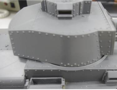
fit upper turret hull to proper position before glue is cured
turret hull can be removed when super glue is cured
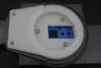
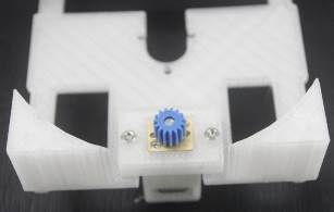
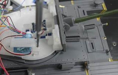
Fit
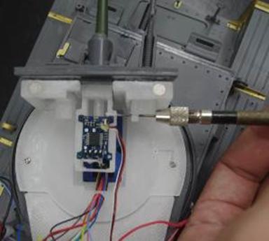
D-Shaft Gear<F3> to geared motor<F2>, wire 2-P cable to motor lead and
then plug cable to
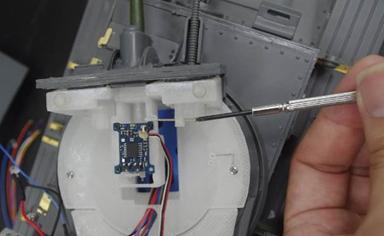
Put two nuts on turret motor assembly and bolt motor assembly from the bottom
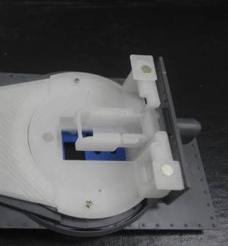
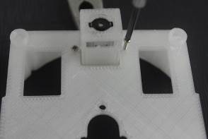
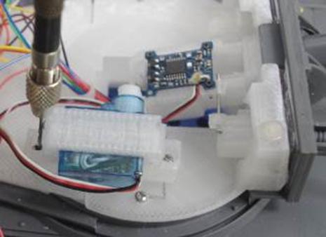
bolt slip ring<F10> with Screw<???>
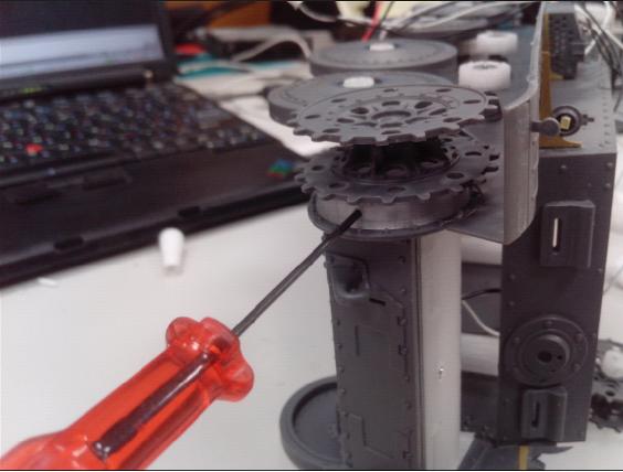
Fit turret motor assembly to tank chassis upper hull
make sure turret gear can be driven smoothly
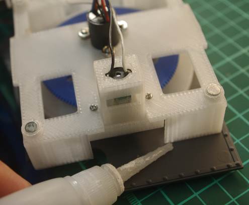
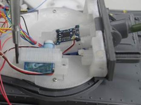
Glue turret motor assembly to tank chassis upper hull by super glue; also glue four magnets to four holes on turret motor assembly.
Glue four magnets to four holes on upper hull fixture<F8>
fit to turret motor assembly; apply super glue on the bottom and fit to tank chassis lower hull before glue is cured.
when glue is cured, make 1.5mm hole and bolt it
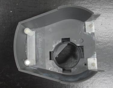
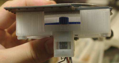
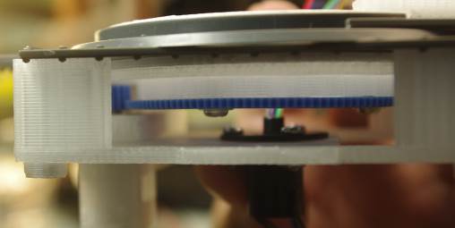
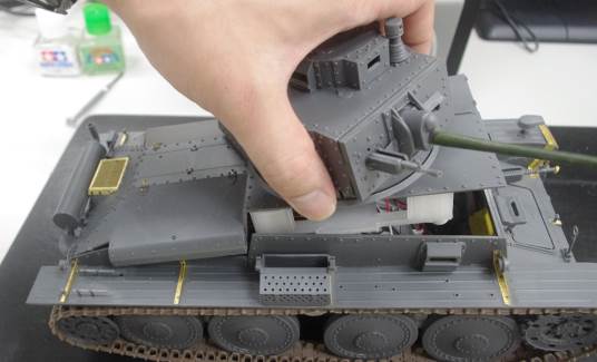
The way to fit upper turret hull
|
|
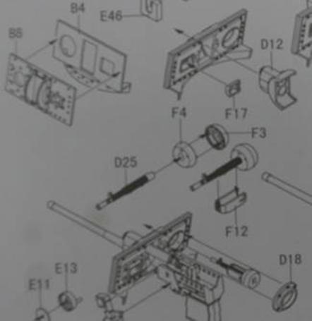
Main Gun、GUN ELEVATE、Gun Elevation、Machine gun
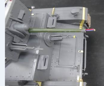
Drill through gun barrel with
Fit gun breech<G2> to gun mantlet(D12), not glue is required, glue gun barrel to gun barrel recoil adaptor<G3>
Insert <G3> to gun breech<G2>
Bolt main gun to gun carriage with screw<???>
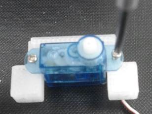
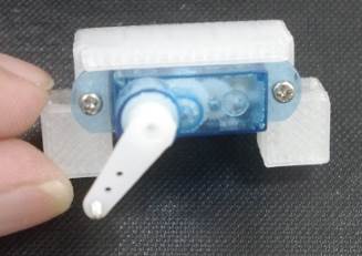
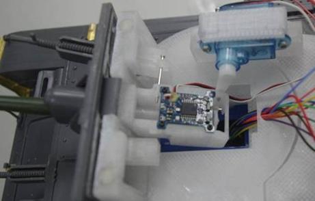
Fit recoil servo<G1> to gun breech
Make 0.8mm hole and bolt it with M1.0 screw, plug servo cable to J2 on TK35
Insert slip ring cable to cable guide opening
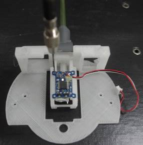
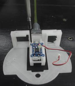
Solder SMD white light LED for main gun flash, and connect to J3 on TK35
Like main gun, drill thought machine gun barrel, insert light guide
Make hole on gun breech,
Bolt MG breech to main gun breech
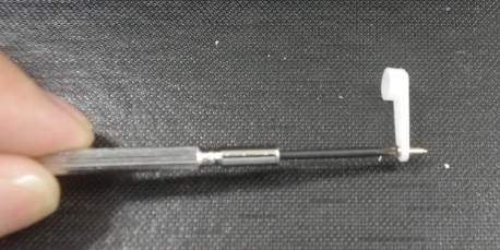
Bolt M1.2*7 screw to elevation servo arm
Bolt
elevation
Bolt
|
|
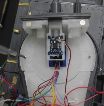
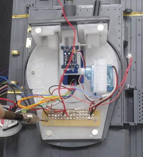
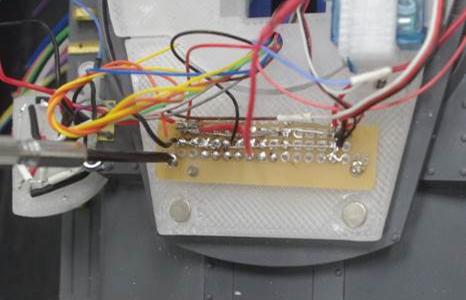
Make 1.0mm hole on turret floor and bolt etched prototyping board<D3> on it.
Wire all positive node together, such as main gun LED J3 (+),machine gun LED CN9-1(+),IR LED_CN2-2(+) Wire all 5V node together, such as barrel recoil servo (+),gun elevation servo J4(+),IR battle receiver CN2-1(+), Wire all ground node together, such as barrel recoil servo (-),gun elevation servo J4(-),IR battle receiver CN2-1(-).
|